MegaSquirt for the Mk 4 Toyota Supra, and other non VVTi Toyota 2JZ-GTE and 2JZ-GE applications
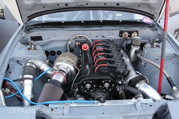
The 2JZ engine gave the Toyota Supra a reputation as one of the top Japanese performance cars of the 1990s, and has also been a popular motor to swap into other platforms. DIYAutoTune’s 240SX land speed car is running a heavily modified 2JZ-GE, shown below. MegaSquirt can let you tune these engines for virtually any modification you can throw at them!
For an easy plug and play installation for your Toyota Supra (or a Lexus SC300), check out our MS3Pro PNP – a direct plug-in engine management system that uses the factory wiring.

Applications:
- 1993-1998 Toyota Supra turbo (JZA80)
- 1993-1997 Toyota Supra non turbo (JZA80)
- 1992-1997 Lexus SC300
- This will also fit some GS300 and Aristo applications.
This articles does not cover the VVTi version of this engine, which uses significantly different electronics. Contact our support if you’d like help there!
Level of control: Full standalone fuel and ignition control. Automatic transmission control will require additional components.
ECU choices:
We recommend running your 2JZ Toyota Supra on the MS3 or preferably MS3Pro if your budget will permit. This will allow for controlling the 2JZ-GTE’s sequential coil on plug ignition, sequential injection, and additional features like traction control – a very handy thing to have when your turbo Supra is putting down big power numbers! We’ve made it EASY to do this by the way — With the MS3Pro PNP Toyota Supra 2JZ / 2JZGTE Plug and Play ECU!
An MS2 engine management system can run this engine with bank to bank fueling. These can run six channel coil on plug as well, but as this uses up almost all available I/O, we recommend using three spark outputs and firing the coils in pairs.
The MicroSquirt is able to run the engine in bank to bank fueling with three spark output channels. However, it does not have an output to run the 2JZ stepper IAC valve, so you will need to find a different way to set up idle control. We recommend the new AMP’d MicroSquirt for six cylinder applications.
These links will take you to the individual write-ups for different options.
- MS3Pro PNP Toyota Supra 2JZ / 2JZGTE Plug and Play ECU – We did all the work — standalone engine management systems don’t get any easier!
- Check out the MS3Pro PNP Install docs for the NK4 Toyota Supra here!
- Note that the MS3Pro PNP does not require any internal modifications or wiring changes. If you run into a write-up that involves soldering inside the ECU or similar work, it’s for a different MegaSquirt version.
- MS3Pro (includes Gen 1, EVO, and Ultimate) – full featured wire-in standalone ECU
- MS3 V3.0 kit with MS3X
- MS3 V3.57 with MS3X
- MS2 V3.0 kit
- MS2 V3.57
- MicroSquirt
You can also use a MicroSquirt to control the 4 speed A340E or A341E automatic that was often paired with the non-VVTi engines. Toyota introduced a 6 speed automatic at about the same time as the VVTi engines. For 6 speed applications, you would need to install the MegaSquirt in parallel with the stock ECU to allow the stock electronics to control the transmission.

MS3Pro PNP – 2JZ-GTE Toyota Supra (MK4 – JZA80) Plug and Play ECU!
This just makes it easy, it’s almost like cheating. Unplug your factory ECU, plug the MS3Pro PNP for the MK4 Toyota Supra in, set base timing, fire the car up, and you’re ready to fine tune for your engine’s exact needs. We’ve done ALL the hard work for you. Just plug it in!!!
Below we’ll get into all of the wire in options, from the MS3Pro to hand-built kit MegaSquirt ECUs. We think most of you though are likely to thoroughly appreciate this MS3Pro PNP though– we did the work so you can just start playing!!!!
MS3Pro
All wire-in MS3Pro ECUs use the same settings and wiring for this application. MS3Pros do not require any internal modifications.
Wiring
For the most part, you’ll be using the wiring in section 4 of the documentation for your particular MS3Pro version. These notes cover 2JZ specific wiring.
- Toyota calls the crank sensor the NE sensor; it is on the crank for the 2JZ-GTE but in the distributor for a 2JZ-GE The NE and G sensors share a common ground. Connect NE+ to the CKP+ wire (pin 6) and G- to the CKP- wire (pin 15) on the MS3Pro white connector.
- There are two camshaft position sensors, which Toyota calls G1 and G2. You’ll only use G1. The MS3Pro’s camshaft position sensor signal conditioner works great with about 90% of these sensors, but sometimes production tolerances mean you run into one that has noise issues while cranking. If you run into these issues, an AXM-120 VR conditioner will do an excellent job of cleaning up the noise.
- If using the MS3Pro built in VR conditioner, connect CMP+ (white connector pin 26) to G1 and CMP- (white connector pin 27) to G-.
- If using the AXM-120 module, connect AXM-120 pin 1 to G1, AXM-120 pin 2 to G-, and AXM-120 pin 5 to MS3Pro white connector pin 26 for CMP+. Do not connect CMP- to anything if using this module.
- These cars use a six wire stepper type IAC valve. For a wire-in installation, we recommend disconnecting the power feed to the IAC – this will reduce the odds of backfeeding power to the ECU with the key off.
- The stock injectors on a 2JZ-GTE are low impedance. For an MS3Pro EVO or first generation, you will need to use the factory injector resistor pack with stock injectors, but can remove the resistor pack if you swap to high impedance injectors. If you are using an MS3Pro Ultimate, you can bypass the resistor pack. Non turbo models used high impedance injectors and do not require a resistor pack.
- Factory coil on plug ignitions will require using the original ignition module. If you are using a distributor, connect MS3Pro spark output A to the IG-T wire on the Toyota ignition module.
- The 2JZ uses a standard inline six 1-5-3-6-2-4 firing order. The spark and ignition outputs match to the cylinders according to firing order:
- Spark / fuel output A – cylinder 1
- Spark / fuel output B – cylinder 5
- Spark / fuel output C – cylinder 3
- Spark / fuel output D – cylinder 6
- Spark / fuel output E – cylinder 2
- Spark / fuel output F – cylinder 4
TunerStudio settings for MS3Pro
Use the following settings under Ignition Options / Wheel Decoder.
- Spark mode: Toothed Wheel
- HEI / GMDIS, TFI, C3I Options: Off
- Ignition Input Capture: Falling Edge *
- Spark output: Going High
- Number of coils:
- Coil on plug for a 2JZ-GTE
- Single coil for a 2JZ-GE stock distributor
- Spark hardware in use: Spark
- Cam input: CMP
- Trigger wheel arrangement: Dual wheel
- Trigger wheel teeth: 12
- Tooth #1 angle: 16 (confirm with a timing light)
- Wheel speed: Crank wheel
- Second trigger active on: Falling edge *
- And every rotation of: Cam
- Toyota Multiplex: Off
- Dwell type: Standard dwell
- Nominal dwell: 2.0 for stock coils
- Toyota ignitions tend to misfire if you use too much dwell.
* Certain adjustable cam gear settings (for a 2JZ-GTE) or distributor tolerances (for a 2JZ-GE) may require triggering on a different edge. If this is the case, you are likely to have the engine start fine, but have a loss of sync in a particular RPM band accompanied by a timing jump. If you run into this case, you may need some trial and error to determine what trigger edges to use. You will need to check the timing with a timing light any time you change the ignition input capture or second trigger active edge and adjust the tooth #1 angle, if necessary.
Suggested parts for MS3Pro installation
- MS3Pro EVO with 8′ wiring harness or MS3Pro Ultimate with 8′ wiring harness
- AXM-120 VR conditioner
- Wideband O2 sensor system
MS3 V3.0 with MS3X
Configuring the MS3 V3.0
You will need to build the main board for a VR conditioner. Jumper TachSelect to VRIN, and TSEL to VROUT.
On the MS3X board, make sure the JP7 jumper is not connected. Set it on one pin of the jumper for safekeeping.
You may need to adjust the VR trim pots to match the sensors.
Wiring
- Toyota calls the crank sensor in the Supra the NE sensor; it is on the crank for the 2JZ-GTE but in the distributor for a 2JZ-GE The NE and G sensors share a common ground. Connect NE+ to the main board crank input on pin 24 and G- to sensor ground
- There are two camshaft position sensors, which Toyota calls G1 and G2. You’ll only use one. You can usually get the VR trim pots adjusted to match, but sometimes production tolerances mean you run into one that has noise issues while cranking no matter how you adjust the trim pots. If you run into these issues, an AXM-120 VR conditioner will do an excellent job of cleaning up the noise.
- If using the MS3X built in VR conditioner, connect G1 to the MS3X cam input on pin 32.
- If using the AXM-120 module, connect AXM-120 pin 1 to G1, AXM-120 pin 2 to G-, and AXM-120 pin 5 to MS3X pin 32.
- These cars use a six wire stepper type IAC valve. For a wire-in installation, we recommend disconnecting the power feed to the IAC – this will reduce the odds of backfeeding power to the ECU with the key off.
- The stock injectors on a 2JZ-GTE are low impedance. You will need to use the factory injector resistor pack with stock injectors, but can remove the resistor pack if you swap to high impedance injectors. Non turbo models used high impedance injectors and do not require a resistor pack.
- Factory coil on plug ignitions will require using the original ignition module. If you are using a distributor, connect MS3X spark output A to the IG-T wire on the Toyota ignition module.
- The 2JZ uses a standard inline six 1-5-3-6-2-4 firing order. The MS3X spark and ignition outputs match to the cylinders according to firing order:
- Spark / fuel output A – cylinder 1
- Spark / fuel output B – cylinder 5
- Spark / fuel output C – cylinder 3
- Spark / fuel output D – cylinder 6
- Spark / fuel output E – cylinder 2
- Spark / fuel output F – cylinder 4
TunerStudio settings for MS3 V3.0
Use the following settings under Ignition Options / Wheel Decoder.
- Spark mode: Toothed Wheel
- HEI / GMDIS, TFI, C3I Options: Off
- Ignition Input Capture: Falling Edge *
- Spark output: Going High
- Number of coils:
- Coil on plug for a 2JZ-GTE
- Single coil for a 2JZ-GE stock distributor
- Spark hardware in use: MS3X Spark
- Cam input: MS3X Cam In
- Trigger wheel arrangement: Dual wheel
- Trigger wheel teeth: 12
- Tooth #1 angle: 16 (confirm with a timing light)
- Wheel speed: Crank wheel
- Second trigger active on: Falling edge *
- And every rotation of: Cam
- Toyota Multiplex: Off
- Dwell type: Standard dwell
- Nominal dwell: 2.0 for stock coils
- Toyota ignitions tend to misfire if you use too much dwell.
* Certain adjustable cam gear settings (for a 2JZ-GTE) or distributor tolerances (for a 2JZ-GE) may require triggering on a different edge. If this is the case, you are likely to have the engine start fine, but have a loss of sync in a particular RPM band accompanied by a timing jump. If you run into this case, you may need some trial and error to determine what trigger edges to use. You will need to check the timing with a timing light any time you change the ignition input capture or second trigger active edge and adjust the tooth #1 angle, if necessary.
Suggested parts for MS3 V3.0 installation
- MS3 V3.0 kit or MS3 V3.0 kit with 4 bar MAP upgrade
- MS3X expansion board
- JimStim test board kit
- JimStim power supply
- MegaSquirt 8′ wiring harness
- MS3X 8′ wiring harness
- MS3 tuning cable
- Wideband O2 sensor system
MS3 V3.57 with MS3X
Configuring the MS3 V3.57
You will need to set the main board for a VR conditioner. Jumper JP1 in the 1-2 position and J1 in the 3-4 position.
On the MS3X board, make sure the JP7 jumper is not connected. Set it on one pin of the jumper for safekeeping.
You may need to adjust the VR trim pots to match the sensors.
Wiring
- Toyota calls the crank sensor the NE sensor; it is on the crank for the 2JZ-GTE but in the distributor for a 2JZ-GE The NE and G sensors share a common ground. Connect NE+ to the main board crank input on pin 24 and G- to sensor ground
- There are two camshaft position sensors, which Toyota calls G1 and G2. You’ll only use one. You can usually get the VR trim pots adjusted to match, but sometimes production tolerances mean you run into one that has noise issues while cranking no matter how you adjust the trim pots. If you run into these issues, an AXM-120 VR conditioner will do an excellent job of cleaning up the noise.
- If using the MS3X built in VR conditioner, connect G1 to the MS3X cam input on pin 32.
- If using the AXM-120 module, connect AXM-120 pin 1 to G1, AXM-120 pin 2 to G-, and AXM-120 pin 5 to MS3X pin 32.
- These cars use a six wire stepper type IAC valve. For a wire-in installation, we recommend disconnecting the power feed to the IAC – this will reduce the odds of backfeeding power to the ECU with the key off.
- The stock injectors on a 2JZ-GTE are low impedance. You will need to use the factory injector resistor pack with stock injectors, but can remove the resistor pack if you swap to high impedance injectors. Non turbo models used high impedance injectors and do not require a resistor pack.
- Factory coil on plug ignitions will require using the original ignition module. If you are using a distributor, connect MS3X spark output A to the IG-T wire on the Toyota ignition module.
- The 2JZ uses a standard inline six 1-5-3-6-2-4 firing order. The MS3X spark and ignition outputs match to the cylinders according to firing order:
- Spark / fuel output A – cylinder 1
- Spark / fuel output B – cylinder 5
- Spark / fuel output C – cylinder 3
- Spark / fuel output D – cylinder 6
- Spark / fuel output E – cylinder 2
- Spark / fuel output F – cylinder 4
TunerStudio settings for MS3 V3.57
Use the following settings under Ignition Options / Wheel Decoder.
- Spark mode: Toothed Wheel
- HEI / GMDIS, TFI, C3I Options: Off
- Ignition Input Capture: Falling Edge *
- Spark output: Going High
- Number of coils:
- Coil on plug for a 2JZ-GTE
- Single coil for a 2JZ-GE stock distributor
- Spark hardware in use: MS3X Spark
- Cam input: MS3X Cam In
- Trigger wheel arrangement: Dual wheel
- Trigger wheel teeth: 12
- Tooth #1 angle: 16 (confirm with a timing light)
- Wheel speed: Crank wheel
- Second trigger active on: Falling edge *
- And every rotation of: Cam
- Toyota Multiplex: Off
- Dwell type: Standard dwell
- Nominal dwell: 2.0 for stock coils
- Toyota ignitions tend to misfire if you use too much dwell.
* Certain adjustable cam gear settings (for a 2JZ-GTE) or distributor tolerances (for a 2JZ-GE) may require triggering on a different edge. If this is the case, you are likely to have the engine start fine, but have a loss of sync in a particular RPM band accompanied by a timing jump. If you run into this case, you may need some trial and error to determine what trigger edges to use. You will need to check the timing with a timing light any time you change the ignition input capture or second trigger active edge and adjust the tooth #1 angle, if necessary.
Suggested parts for MS3 V3.57 installation
- MS3 V3.57 with MS3X expansion board
- JimStim test board kit
- JimStim power supply
- MegaSquirt 8′ wiring harness
- MS3X 8′ wiring harness
- MS3 tuning cable
- Wideband O2 sensor system
MS2 V3.0
Configuring the MS2 V3.0
This application requires building the board for two VR conditioners and three logic level spark outputs. The Zeal daughterboard is the easiest way to get the required outputs on a V3.0 board.
Note that this build gives up the CANbus outputs to get all I/O on the main connector. If you have the JS6 to SPR1 and JS8 to SPR2 jumpers, you will need to remove these.
First, we’ll cover how to build a Zeal Engineering Daughterboard.
Daughterboard Assembly
- Install all resistors in the indicated locations and solder into place.
- We have found that the second signal conditioner works better with the ground jumper installed in the two holes next to U2. Install a length of snipped resistor lead to bridge these holes, and solder into place.
- Install diodes D2 through D5, with the banded end towards the lower end of the card.
- Install C2, C3, C4, and C6.
- Install U1 and U2.
- Install C7.
- Install the Q1 through Q4 transistors, with the flat side on the transistor pointing to the flat side of the silk screen.
- Install Q5, again taking care to match its outline to the silk screen.
- Install C1 and C5. These capacitors are polarized; the long lead goes in the + hole and the white striped side goes in the other hole.
- Note that the VR connections (which you will hook up in the next steps) have the positive terminal next to the VR1 or VR2 marking, and the negative terminal furthest away from that marking.
Main board modifications
- Build the ECU up to trigger from the VR Input. Jumper TachSelect to VRIN and TSEL to VROUT.
- We will need three ignition outputs, each with a 5 volt pull up.
- Run a 1K resistor from the 5 volt source in the proto area or the right side of R24 to the top (negative) lead of D14, and run a jumper wire from the negative lead of D14 to IGN. This is spark output A, on pin 36.
- Run a 1K resistor from the 5 volt source in the proto area or the right side of R28 to the top (negative) lead of D16, and run a jumper wire from the negative lead of D16 to SPR4. This is spark output B, on pin 6.
- Run a 1K resistor from the 5 volt source in the proto area or the right side of R25 to the top (negative) lead of D15, and run a jumper wire from the negative lead of D15 to SPR3. This is spark output C, on pin 5.
- Now it’s time to connect the daughterboard to the main board. Use these connections:
Daughterboard connection Main board connection 12V S12 5V S5 GND Proto GND GND SG VR2 + SPR2 VR2 – No connection (uses internal ground) VR2 Out JS10 IDLIN Bottom end of R19 IDLOUT Banded end of D8 IN1 JS11 OUT1 (Tach output) SPR1
Wiring
- Toyota calls the crank sensor the NE sensor; it is on the crank for the 2JZ-GTE but in the distributor for a 2JZ-GE The NE and G sensors share a common ground. Connect NE+ to the crank input on pin 24 and G- to sensor ground.
- There are two camshaft position sensors, which Toyota calls G1 and G2. You’ll only use one. Connect G1 to pin 4.
- These cars use a six wire stepper type IAC valve. For a wire-in installation, we recommend disconnecting the power feed to the IAC – this will reduce the odds of backfeeding power to the ECU with the key off.
- The stock injectors on a 2JZ-GTE are low impedance. You will need to use the factory injector resistor pack with stock injectors or use PWM current limiting to drive these injectors. Non turbo models used high impedance injectors and do not require a resistor pack or PWM current limiting.
- Factory coil on plug ignitions will require using the original ignition module. If you are using a distributor, connect pin 36 / spark output A to the IG-T wire on the Toyota ignition module.
- The 2JZ uses a standard inline six 1-5-3-6-2-4 firing order. You’ll wire the spark outputs in pairs
- Pin 36 / spark output A – cylinder 1 and 6
- Pin 6 / spark output B – cylinder 2 and 5
- Pin 5 / spark output C – cylinder 3 and 4
- These mods have a tach output on pin 3 of the DB37 – set this to use JS11 as a tach output pin.
TunerStudio settings for MS2 V3.0
Use the following settings under Ignition Options / Wheel Decoder.
- Spark mode: Toothed Wheel
- Ignition Input Capture: Falling Edge *
- Spark output: Going Low
- Number of coils:
- Wasted Spark for a 2JZ-GTE
- Single coil for a 2JZ-GE stock distributor
- Spark A output pin: D14
- Cam input: JS10
- Trigger wheel arrangement: Dual wheel
- Trigger wheel teeth: 12
- Tooth #1 angle: 16 (confirm with a timing light)
- Wheel speed: Crank wheel
- Second trigger active on: Falling edge *
- And every rotation of: Cam
- Toyota Multiplex: Off
- Dwell type: Standard dwell
- Nominal dwell: 2.0 for stock coils
- Toyota ignitions tend to misfire if you use too much dwell.
* Certain adjustable cam gear settings (for a 2JZ-GTE) or distributor tolerances (for a 2JZ-GE) may require triggering on a different edge. If this is the case, you are likely to have the engine start fine, but have a loss of sync in a particular RPM band accompanied by a timing jump. If you run into this case, you may need some trial and error to determine what trigger edges to use. You will need to check the timing with a timing light any time you change the ignition input capture or second trigger active edge and adjust the tooth #1 angle, if necessary.
Suggested parts for MS2 V3.0 installation
- MS2 V3.0 kit or MS2 V3.0 kit with 4 bar MAP upgrade
- Zeal Engineering daughter board kit
- JimStim test board kit
- JimStim power supply
- MegaSquirt 8′ wiring harness
- DB9 straight through tuning cable
- USB-2920 adapter
- Wideband O2 sensor system
MS2 V3.57
Configuring the MS2 V3.57
This application requires building the board for two VR conditioners and three logic level spark outputs. The Zeal daughterboard is the easiest way to get the required outputs on a V3.0 board.
Note that this build gives up the CANbus outputs to get all I/O on the main connector.
First, we’ll cover how to build a Zeal Engineering Daughterboard.
Daughterboard Assembly
- Install all resistors in the indicated locations and solder into place.
- We have found that the second signal conditioner works better with the ground jumper installed in the two holes next to U2. Install a length of snipped resistor lead to bridge these holes, and solder into place.
- Install diodes D2 through D5, with the banded end towards the lower end of the card.
- Install C2, C3, C4, and C6.
- Install U1 and U2.
- Install C7.
- Install the Q1 through Q4 transistors, with the flat side on the transistor pointing to the flat side of the silk screen.
- Install Q5, again taking care to match its outline to the silk screen.
- Install C1 and C5. These capacitors are polarized; the long lead goes in the + hole and the white striped side goes in the other hole.
- Note that the VR connections (which you will hook up in the next steps) have the positive terminal next to the VR1 or VR2 marking, and the negative terminal furthest away from that marking.
Main board modifications
- Set the ECU up to trigger from the VR Input. Put the JP1 jumper in the 1-2 position, and the J1 jumper in the 3-4 position.
- We will need three ignition outputs, each with a 5 volt pull up.
- Connect PAD1 to the center hole of Q16 – remove Q16 if fitted. This is spark output A, on pin 36.
- Connect PAD3 to SPR4. This is spark output B, on pin 6.
- Conned PAD2 to SPR3. This is spark output C, on pin 5.
- Now it’s time to connect the daughterboard to the main board. Use these connections:
Daughterboard connection Main board connection 12V S12 5V S5 GND Proto GND GND SG VR2 + DB15 pin 3 VR2 – No connection (uses internal ground) VR2 Out JS10 IDLIN Bottom end of R19 IDLOUT Banded end of D8 IN1 JS11 OUT1 (Tach output) DB15 pin 5
Wiring
- Toyota calls the crank sensor the NE sensor; it is on the crank for the 2JZ-GTE but in the distributor for a 2JZ-GE The NE and G sensors share a common ground. Connect NE+ to the crank input on DB37 pin 24 and G- to sensor ground.
- There are two camshaft position sensors, which Toyota calls G1 and G2. You’ll only use one. Connect G1 to DB15 pin 3.
- These cars use a six wire stepper type IAC valve. For a wire-in installation, we recommend disconnecting the power feed to the IAC – this will reduce the odds of backfeeding power to the ECU with the key off.
- The stock injectors on a 2JZ-GTE are low impedance. You will need to use the factory injector resistor pack with stock injectors or use PWM current limiting to drive these injectors. Non turbo models used high impedance injectors and do not require a resistor pack or PWM current limiting.
- Factory coil on plug ignitions will require using the original ignition module. If you are using a distributor, connect DB37 pin 36 / spark output A to the IG-T wire on the Toyota ignition module.
- The 2JZ uses a standard inline six 1-5-3-6-2-4 firing order. You’ll wire the spark outputs in pairs:
- DB37 pin 36 / spark output A – cylinder 1 and 6
- DB37 pin 6 / spark output B – cylinder 2 and 5
- DB37 pin 5 / spark output C – cylinder 3 and 4
- These mods have a tach output on pin 5 of the DB15 – set this to use JS11 as a tach output pin.
TunerStudio settings for MS2 V3.57
Use the following settings under Ignition Options / Wheel Decoder.
- Spark mode: Toothed Wheel
- Ignition Input Capture: Falling Edge *
- Spark output: Going Low
- Number of coils:
- Wasted Spark for a 2JZ-GTE
- Single coil for a 2JZ-GE stock distributor
- Spark A output pin: D14
- Cam input: JS10
- Trigger wheel arrangement: Dual wheel
- Trigger wheel teeth: 12
- Tooth #1 angle: 16 (confirm with a timing light)
- Wheel speed: Crank wheel
- Second trigger active on: Falling edge *
- And every rotation of: Cam
- Toyota Multiplex: Off
- Dwell type: Standard dwell
- Nominal dwell: 2.0 for stock coils
- Toyota ignitions tend to misfire if you use too much dwell.
* Certain adjustable cam gear settings (for a 2JZ-GTE) or distributor tolerances (for a 2JZ-GE) may require triggering on a different edge. If this is the case, you are likely to have the engine start fine, but have a loss of sync in a particular RPM band accompanied by a timing jump. If you run into this case, you may need some trial and error to determine what trigger edges to use. You will need to check the timing with a timing light any time you change the ignition input capture or second trigger active edge and adjust the tooth #1 angle, if necessary.
Suggested parts for MS2 V3.57 installation
- Assembled MS2 V3.57
- Zeal Engineering daughter board kit
- JimStim test board kit
- JimStim power supply
- MegaSquirt 8′ wiring harness
- DB9 straight through tuning cable
- USB-2920 adapter
- Wideband O2 sensor system
MicroSquirt
The MicroSquirt can run these engines, but has a limited I/O feature set. In particular, it doesn’t have a stepper IAC valve driver. Your best bet for idle speed control is to use a 2 wire IAC valve such as the ones used on most mid 1990s VW 4 cylinder applications. These valves use hose barb fittings and are easier to adapt to other engines than IAC valves intended to bolt to a throttle body or intake manifold.
The stock 2JZ-GTE injectors, even with the factory resistor pack, will draw more current than standard MicroSquirt injector drivers are rated for. We recommend using an AMP’d MicroSquirt for this application. If installing a standard MicroSquirt, you will want to run high impedance injectors.
Wiring
For the most part, you’ll be using the wiring in section 4 of the documentation for your particular MS3Pro version. These notes cover 2JZ specific wiring.
- Toyota calls the crank sensor the NE sensor; it is on the crank for the 2JZ-GTE but in the distributor for a 2JZ-GE The NE and G sensors share a common ground. Connect NE+ to the VR1+ wire (pin 32) and G- to the VR1- wire (pin 33).
- There are two camshaft position sensors, which Toyota calls G1 and G2. You’ll only use G1. The MicroSquirt’s camshaft position sensor signal conditioner works great with about 90% of these sensors, but sometimes production tolerances mean you run into one that has noise issues while cranking. If you run into these issues, an AXM-120 VR conditioner will do an excellent job of cleaning up the noise.
- If using the MicroSquirt’s built in VR conditioner, connect VR2+ (pin 4) to G1 and VR2- (pin 21) to G-.
- If using the AXM-120 module, connect AXM-120 pin 1 to G1, AXM-120 pin 2 to G-, and AXM-120 pin 5 to VR2+ (pin 4). Do not connect VR2- to anything if using this module.
- The stock injectors on a 2JZ-GTE are low impedance. The AMP’d MicroSquirt can run these using the stock resistor pack. For a regular MicroSquirt, switch to high impedance injectors. The naturally aspirated 2JZ-GE injectors are high impedance and would not need to be changed.
- Factory coil on plug ignitions will require using the original ignition module. If you are using a distributor, connect MicroSquirt spark output A to the IG-T wire on the Toyota ignition module.
- The 2JZ uses a standard inline six 1-5-3-6-2-4 firing order. You’ll wire the spark outputs in pairs:
- Pin 12 / spark output A – cylinder 1 and 6
- Pin 11 / spark output B – cylinder 2 and 5
- Pin 17 (WLED) / spark output C – cylinder 3 and 4
- If using an AMP’d MicroSquirt, switch on the pull up for spark output C with the internal DIP switch. For a regular MicroSquirt, tee a 1K resistor in between the output on pin 17 and VREF (pin 28).
TunerStudio settings for MicroSquirt
Use the following settings under Ignition Options / Wheel Decoder.
- Spark mode: Toothed Wheel
- Ignition Input Capture: Falling Edge *
- Spark output: Going High
- Number of coils:
- Wasted Spark for a 2JZ-GTE
- Single coil for a 2JZ-GE stock distributor
- Spark hardware in use: IGN1
- Cam input: Cam Input
- Trigger wheel arrangement: Dual wheel
- Trigger wheel teeth: 12
- Tooth #1 angle: 16 (confirm with a timing light)
- Wheel speed: Crank wheel
- Second trigger active on: Falling edge *
- And every rotation of: Cam
- Toyota Multiplex: Off
- Dwell type: Standard dwell
- Nominal dwell: 2.0 for stock coils
- Toyota ignitions tend to misfire if you use too much dwell.
* Certain adjustable cam gear settings (for a 2JZ-GTE) or distributor tolerances (for a 2JZ-GE) may require triggering on a different edge. If this is the case, you are likely to have the engine start fine, but have a loss of sync in a particular RPM band accompanied by a timing jump. If you run into this case, you may need some trial and error to determine what trigger edges to use. You will need to check the timing with a timing light any time you change the ignition input capture or second trigger active edge and adjust the tooth #1 angle, if necessary.
Suggested parts for MicroSquirt installation
- AMP’d MicroSquirt with 8′ harness
- GM-type 3 bar MAP sensor and 6″ pigtail connector
- USB-2920 adapter
- AXM-120 VR conditioner
- Wideband O2 sensor system
MicroSquirt transmission control
You can add a MicroSquirt loaded with transmission control firmware to take control over the A340E or A341E four speed automatic. The MicroSquirt will connect over CAN to any MS2 or MS3 based ECU controlling the engine so it can share tuning and data with the engine controller. You will need to build an extra circuit for the Toyota shift lever position input. See section 5.3 of the MicroSquirt transmission control manual for full wiring details. Since the MicroSquirt outputs are ground switched and many of Toyota’s solenoids need 12 volts, you can use our four channel high side driver to convert the outputs to 12 volts.
Suggested parts for MicroSquirt transmission control
- MicroSquirt with 8′ harness
- HSD-4 high side driver
- USB-2920 USB adapter
- Note that if you have already ordered a USB-2920 for use with an MS2 or MicroSquirt, you will not need a second adapter for the transmission control.