From Carb to EFI on just a fistful of dollars…
Updated 3/3/09 – Added dyno chart showing comparison of readings taken on old vs new dyno.
Objective of this Article
This article will walk you through the process of installing a MegaSquirt EFI system on a classic carb’d vehicle attempting to go the least expensive route possible using junkyard parts and DIY ingenuity. We’ll be using an MegaSquirt-II v3.57 ECU. We’re converting the car over to an EFI ‘fuel only’ setup leaving control of the ignition in the hands of the old school distributor for now. We’ll take control of ignition in a separate article, but like we recommend to first time EFIer’s, it’s easier to take control of fuel first, then ignition. Fuel control is fairly easy and rewarding. After this taking control of ignition isn’t that hard either and will continue the EMS (Engine Management System) learning process and the rewards of using an EMS. That will come in part two.
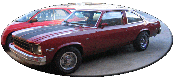
We chose a 1977 Chevy Nova with a 350 small block as our subject, but the principles laid out here can be used just the same on a big block Chevy, or a Ford, Dodge small or big block engine, inline engine, a foreign motor… a motor is a motor is a motor. The only trick becomes finding a suitable intake and/or TBI and/or TBI adapter. Or fabricating your own. For the more common engines, off the shelf adapters and intakes abound. For owners of the more obscure stuff, well, you’re probably a pretty good fabricator by now anyways eh?
Note that though this is one example of a Carb-to-EFI conversion using a MegaSquirt-II this system can be used on just about any vehicle, using TBI or Multi-Port injection, even Central Port injection if you so choose. We’ll be doing further articles (MPFI soon) but you’ll certainly find the MSExtra Manuals an invaluable resource that our guides are meant to supplement and not replace.
Installing the Electronics
MegaSquirt ECU, Relay Board, and a couple sensors…
Mounting the ECU, Relay Board, and Fusebox
First things first. I found a good spot under the hood on the firewall for the Relay Board, and another inside the cabin on the kick panel for the MegaSquirt. I chose very visible spots for both boxes, you can be more stealthy of course though I had no reason to be ;). I physically mounted the two boxes. Drilled a hole out in the firewall and passed the relay cable through using a grommet to protect the cable. I had also installed a couple of Innovate TC-4’s in this car for individual cylinder (all 8) EGT monitoring. That’s really only needed in full on race conditions or tuning a motor for such conditions, or on R&D projects such as this car where I intend to swap several different EFI systems on and measure the differences in individual cylinder air/fuel distribution.
Here’s a little video showing how to pass the relay cable through the firewall.
Notice the power wiring for the fuse block is already run behind this:
Wiring Main Power to the Fusebox
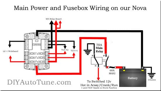
Next I installed a 70amp Main Power Relay and Fuse Block that I would be using to power all of the engine management and datalogging goodies I had planned for this car. The fuse block gets a 10ga ground directly from the engine block (battery (-) would have been good too). It gets it’s 12v feed via another 10ga wire directly to the Positive terminal of the battery with a 60a MAXI type fuse right at the battery, then the 10ga wire is routed to and through the 70 amp relay so the entire fuse block is switched 12v. I ran a trigger wire to the relay from the factory fuse block near the drivers feet. There’s conveniently a spade terminal on the fuse block labeled ‘IGN’ that’s hot in crank and run, just like I needed. You may not have this, but what’s important is that the Relay Board and therefore the ECU/Fuel pump/Injectors, etc have power both when cranking, and when running. Some circuits may be powered in one or the other but not both, you need both.
Click this image for a larger view
Note– This wiring above is really all additional to what is normally required. This is what we did to support the additional goodies in this car, the two TC4 EGT amplifiers, the LC-1, and allowing a bit of room to grow. Had we not needed the TC-4s or the ‘room to grow’, we would have done something simpler.
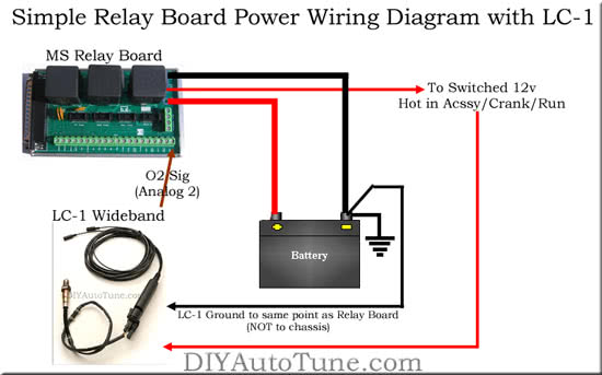
Like this:
Click this image for a larger view
Here in this simplified approach, which is really all most will need, you see the Relay Board’s main power is wired directly to battery 12v and Ground. The 12v Switched position for the relay board’s power is run a switched 12v source that’s hot in accessory, crank and run positions of the key. That’s important or you might not have power when cranking, so test it! If you’re not installing a wideband yet, that’s it, you’re done with your power wiring. If you are, then the above shows simple wideband wiring too. You ALWAYS want to ground your wideband (and any analog wideband gauge) at the same point as your ECU to prevent what’s known as a ground offset which can effect the accuracy of your readings. In this case that’s the battery where we’ve grounded the Relay Board, so bring the ground back there. The 12v supply is less picky, but you’ve probably already found a good switched source for 12v so as long as it can handle the load (maybe 5a) then you can use it for your wideband too. Then final wire is the signal wire out from the wideband and back to the MegaSquirt. This would be the brown wire on the LC-1, to the ‘o2’ terminal on the Relay Board.
Wiring Power to the Relay Board
Next, power and ground were wired up to the relay board. This required the third and final hole in the firewall that I drilled large enough for my EGT wiring an anything else I’d be passing through as well, also using a grommet of course. The relay board was wired to the main fuse block’s ground and 12v switched supply. I started with a 5amp fuse in this circuit, though I expect to have to increase that. So that covers the ground for the Relay Board, and the Switched 12v for the Relay Board. The final connection is the permanent 12v connection, this should go straight to the battery 12v post just on the ‘protected’ side of that 60A MAXI fuse. I did this by connecting it together with the Main power input to the 70A Relay as can be seen in the above picture of the relay.
Getting a TACH Signal
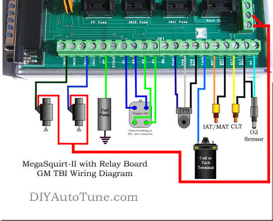
Next I wired up the tach signal to Relay board from the distributor’s ‘TACH’ terminal. I used some of our shielded wiring for this as there will be a ton of high voltage/current induced noise around the distributor and wires and I wanted to avoid that if possible. This is a convenient pickup point on the 4-pin HEI distributors to grab a tach signal for a fuel only EMS installation, though you should try and avoid direct contact of your tach wire with the plug wires. Crimp a spade terminal on the center conductor of the shielded wire. Strip back the shielding from this end and cut it off so that it doesn’t contact the crimp. Heat shrink this connection to protect it. Use split loom to cover the wire to prevent direct contact, route it away from the plug wires as much as possible, and at the relay board side, connect the center conductor to the TACH terminal, and connect the shielding to one of the sensor return terminals to ground the shielding. You only want the shielding grounded on one end, not both.
The following diagram I could have put in many places in this article, but I’ll go ahead and put it here where I’m discussing the first of the wiring that would need to go back to the relay board from the engine (tach signal). You’ll refer to this for all of the later components as well though, sensors, injectors, IAC, etc. Everything you see here:
Note the above wiring diagram shows one difference from how I wired things up– this shows how to use a 2-wire narrowband o2 sensor. I highly recommend a wideband o2 sensor such as the Innovate LC-1 as when it comes to tuning time nothing else but a wideband will do. Use the information in the ‘simplified power wiring’ diagram above for wideband wiring.
MAP/Vacuum Signal to the ECU
Next I routed the MAP signal hose (vacuum line) to the MegaSquirt through a small hole drilled in the firewall just next to where I passed the relay cable through. I connected this to the MegaSquirt and made sure I had enough loose vacuum line in the engine compartment to reach the TBI’s vacuum port I’d be using.
Should I play or should I go?
At this point, you can still drive the car around on the carb, but you can connect to your MegaSquirt with the tuning software and see your RPM and manifold pressure. You can also datalog this if you want and play with the software a bit just getting a feel for things. You don’t have much info yet as you’ve only wired up two inputs, but it’s a start. Pretty cool eh?
Wiring up the CLT Sensor
Ready for more? Install and wire in the CLT sensor. Many intake manifolds have a boss just in front of the thermostat opening where they’re either already tapped, or where you can drill and tap them for a CLT. The Coolant Sensors we offer use a 3/8″-NPT thread. Wire this back to the relay board’s CLT and CLT RET terminals. You can’t wire this particular sensor backwards as it will work either way, but if you run a black wire back on one side go ahead and run it to CLT RET to avoid confusion, that is the ground side of the circuit.
Wideband Oxygen Sensor
Next install and calibrate your wideband o2 system. Though installing a dedicated wideband in the car is optional, it’s highly recommended. We recommend and sell the Innovate Motorsports LC-1, it’s affordable, easy to install if you can follow a few simple directions, easy to calibrate, and does a great job. We use the common fuse block for power and ground, however if you’ve gone a simplified path like many will and wired your relay board straight to the battery then you can wire your wideband just like we did in the diagram above titled “Simple Relay Board Power Diagram with LC-1”.
IAT/MAT – now or later
You could go ahead and wire up an intake air temp sensor too if you want and keep playing around with the software and datalogging, learning a bit about how the car ran on the carb before going any further. Or for that matter I’ve had customers wire up our systems about this far along and use them as datalogging systems only for longer terms, knowing some day they wanted to go EFI but happy to just collect data for the time.
Here’s an easy way to add an MAT/IAT sensor to your stock carb-style air cleaner: (note: the terms MAT and IAT are used interchangeably, meaning Manifold Air Temp, or Intake Air Temp)
So now your MAT/IAT sensor just screws into the bottom of your otherwise stock looking carb-style air cleaner. As it’s internally the same type of sensor as a CLT the wiring polarity doesn’t matter, wire one side to the MAT terminal on the Relay Board, and the other side to the MAT Ret terminal on the relay board. Again, if you choose black for one of the wires, it just makes sense to use that on the return side.
So now what?
At this point, you’re able to datalog all, or nearly all (if you didn’t install the IAT yet), of the inputs required for EFI to function on your car. Again, drive it this way it is for a bit if you’d like and get used to the computer interface and datalogging tools, or just dive into the next section and go EFI!
Installing the TBI System
Finding the TBI bits
Remember our goal here is cheap and as easy as possible. So I hit up the junkyard, found a 1992 GMC 2500 Van with VIN ‘K’ indicating it had a 350 in it, and grabbed the TBI system including the air cleaner, injectors, and a couple feet of the fuel hardlines. Also make sure to get several inches of all wiring and all connectors. Make sure you get the mounting bolts. Cost me $33-34 total. Here’s what I got for that:
Preparing and installing the TBI
I then slapped a TBI adapter plate on my Torker II intake Manifold and bolted the TBI to it. I found the stock mounting bolts were a touch too long. I could have either cut them shorter, or used washers, so I sortof used washers. I found some nuts in my spare jar that were just big enough to slip over the bolts and act as thick washers. Works like a champ ;). Lastly I cut both fuel lines down short leaving just enough that I could clamp the feed and return onto them. Check your o-rings and if they’re in bad shape then replace them (parts store), mine weren’t perfect but were holding together, and they’ve been fine though I may grab some replacements next time I visit the parts store. Make sure you de-burr that fuel line so it won’t damage the hose you clamp to it later nor release any loose metal in the lines at a later date.
Throttle Linkage
So now I’ve got my the TBI bolted up to the manifold, I’ll go ahead and work out my throttle/kickdown linkage before I wire it up. I re-used the stock carb linkage from the Quadrajet, but had to build a spacer to move it back just a bit. The pics below show me holding the throttle wide open with the cable in the WOT position as well, I then measured the difference in the hookup versus hole alignment and made a spacer to move it back that far. Easy enough right?
Fuel Injector Wiring
Next, wire up the injectors. Run 12v Power to each of the injectors on one side, I chose the White and Red wires for this. You can actually crimp these together to a single larger gauge (14-16ga) wire and run that back to one of the ‘Injector 12v’ Terminals on the Relay Board. Then wire the Blue wire up to the INJ1 terminal, and the Green wire up to the INJ2 terminal, both on the Relay Board.
True, if you look closely above there’s only one injector wire run back to the relay board in that picture. OK you caught me with a bad picture. Here’s another pic further along in the process where you can see both run back, one to INJ1 (Blue) and the other to INJ2 (Green). You can also see the Injector 12v wire run back to the relay board here.
Throttle Position Sensor Wiring
Next, wire up the 3-pin Throttle Position Sensor connector on the TBI to the Relay Board. This is simple.
- Grey wire goes to VREF terminal on the Relay Board.
- Blue wire goes to TPS terminal on the Relay Board.
- Black wire goes to TPS RET terminal on the Relay Board.
*You’ll need to calibrate your TPS in the tuning software later. We’ll go over that but I figured I’d mention it here.
Installing and Wiring the IAT/MAT Sensor (if you didn’t already)
Here are a couple of ideas for installing an IAT sensor in a GM TBI system:
First option> In the stock GM TBI collar with the stock GM TBI Air cleaner/snorkel. Very clean appearance, hides the TBI system well, breathes fairly good but not as good as putting one of the other two cleaners (below) on top of the collar. In my case it didn’t quite clear my hood so I tried something else.
Second option> Alternately, you can put the IAT sensor right into the bottom of a carb style air cleaner like so. Then you can set it directly on top of the TBI without the collar, BUT, you will likely loose some top end power without the collar in there. You will gain in the ‘stock-carb-like-appearance-factor’ as the carb-style air cleaner will practically hide the TBI system when sitting that low. But you might suffer a bit in airflow at high RPM. See the next section ‘What to use for an air cleaner?’ for more info.
So now the IAT just screws into the bottom of the otherwise stock looking carb-style air cleaner.
Third Option> So I’ve found I need the collar there. So I’m putting the IAT back in that GM TBI Collar similar to Option 1, and under an air cleaner. Either a stock carb-style round air cleaner, or an aftermarket low profile air cleaner for more hood clearance.
On our 77 Nova I was about 1/2″ short on hood clearance to fit the GM TBI air cleaner sitting on top of this collar. I similarly didn’t have quite enough clearance for a 3″ tall round carb-style cleaner. So since I didn’t want to go to a raised cowl hood, my final solution was a low profile aftermarket foam filter. Cheap and easy, though sacrifices appearance a bit. If I was a bit more determined I could have shortened that collar 1/2″ and used that 3″ carb style cleaner for the best of both world, breathing and appearance.
Back to the original focus of this section, the IAT. When wiring the IAT/MAT sensor, it’s internally the same type of sensor as a CLT so the wiring polarity doesn’t matter, wire one side to the MAT terminal on the Relay Board, and the other side to the MAT Ret terminal on the relay board. Again, if you choose black for one of the wires, it just makes sense to use that on the return side.
What to use for an air cleaner?
I found in dyno testing that you absolutely want to use the riser collar that comes with the TBI unit under your air cleaner. It’s amazing the difference it makes if you pull this puppy out, and it’s a difference most won’t like. This serves more purpose than just raising the filter up, but it also straightens out the path of the airflow as it enters the throttle body. On our test car this was worth only about 4-6whp up at the peak(around 4000rpm), but an amazing 40whp, yes four-zero wheel horsepower near redline at 5300-5400rpm. The air just can’t enter the stock GM throttle body at a right angle like that fast enough to keep up and it severely hinders the flow of the TBI unit without this collar in place.
So what worked the best? Using the collar, with the stock carb-style air cleaner on top and paper filter seemed to work the best, and provides the most carb-like appearance. However with the hood clearance I was working with I’d have to find a seriously short filter to allow me to close the hood this way. I tested both 3″ and 4″ tall filters on the dyno and saw no HP difference, though neither would fit under my hood without surgery.
Pretty much identically following the hp/torque curve of the above was the Edlebrock low profile foam filter. This is short enough to clear the hood, and breathes nearly as well as the tall paper filters above. It may have averaged 1 whp less if that. IMO well worth solving the hood clearance issues unless you like the idea of installing a cowl hood or cutting a hole for a scoop. This is the route I ended up choosing.
The stock ‘black snorkel’ TBI air cleaner came in third– it breathes fairly good up until 5000rpm or so and then fell off loosing horsepower rapidly. Still much better than the final option.
The last option, removing the collar from the TBI and sitting an air cleaner all the way down on the TBI looks fairly carb-like stock, and around town, under 4000rpm will perform very good, but above 4000rpm it’s going to hinder performance significantly. HP/TQ fell way off from about 4000rpm all the way to redline.
Now you need a Fuel System
Installing and Wiring the Fuel Pump and Filters
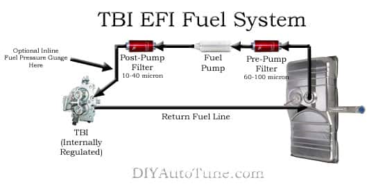
I chose a location just in front of the fuel tank and above the wheel well. I first determined where I wanted to place the pump based on easy inlet and outlet as well as mounting considerations, and then I marked the stock hardline to cut a section out of it where I’d be patching the fuel pump in. I then unbolted and removed the factory hardline from the fuel tank leading up towards the engine bay, drained the fuel out of it, cleaned it off/out and cut it where I had it marked. Deburred it good and then reinstalled the two pieces.
I drilled holes in the framerail for the mounting straps (yes you should use both straps, I only have one on in the picture below). Then I bolted the fuel pump in place, attached a low pressure inlet line to a AN-6 inlet fitting, (could have used a 3/8″ barb fitting but this just felt cleaner), and built a stainless AN -6 line for the outlet (high pressure) side to attach it back to the factory fuel hardline. The last step was to wire the ground connection for the fuel pump to a local chassis bolt and the power connection for the fuel pump to the ‘FP’ terminal on the MegaSquirt Relay Board under the hood. I chased the fuel line up to the engine compartment with this wire, covered it with the smallest split loom I had, and zip tied it all up neatly.
Note– the fuel pump location here is a bit on the high side. I tried and killed a different manufacturer’s pump in this location, the Walbro has held up fine although I would recommend mounting it lower as it’s close to the top of the fuel tank in this install. There just isn’t a great location in front of the fuel tank and clear of the exhaust that I can see. But now that I’ve looked harder, behind the fuel tank attached to the bottom of the trunk area is lower and would get a better gravity feed of fuel and will be where I mount the new pump. (We’re using this car to test all sorts of bits, next up, the SX Performance line of pumps)
Next I installed a small ‘pre pump’ fuel filter just at the outlet of the tank. (Yes this is important.) Note this fuel pickup had a ‘sock’ strainer inside the tank, but it was old and worn and I didn’t want to trust the life of my fuel pump (and potentially my engine) to it. A 60-100 micron stainless filter just outside the tank and before the pump will do a fine job.
Then I installed a second ‘after pump’ 40 Micron fuel filter on the fuel feed line at a factory break in the hard line where there was a worn out rubber line that needed to be replaced anyways (as it wasn’t designed for EFI pressure), just under the passenger side door. The fuel filter had -8 AN male fittings on either side, I used a pair -8 to 3/8″ barb fittings from a local hardware store plumbing dept. to adapt this to 3/8″ barb and clamped it on the line with worm clamps.
Note this fuel filter is very small and not really intended for long term use without servicing. Something along the lines of the SX Performance filters we’re now carrying would be much better suited to this job. The SX Performance 10 micron paper filter anywhere after the pump and before the injectors (before the TBI) will do the trick.
Completing the Fuel System
Now for the fuel return. This car being a 1977 has a very tempting vent tube coming back up from the fuel tank to a charcoal canister under the hood. Resist temptation and don’t repurpose this as a return line. On our test car there is an obstruction that does not allow adequate flow in this line and it does not make a suitable return line. Besides that, it’s venting your fuel tank, and that’s a good thing.
Instead, you’re going to want to add a return line to your fuel tank. Sounds like a pain, but at least in our case it really wasn’t that bad. You’ll want to disconnect the fuel lines and drop the fuel tank. Check out your tank and how much space you have to add a new return line, it doesn’t take much. Remove the locking collar and pull the line assembly out of the tank. (Make sure to clean up the top of the tank first to keep junk from dropping in.)
Now, you can either get a steel fitting and weld in a nipple, carefully making sure the entire apparatus/lines are fuel free first. Or you can do what we did and simply drill a hole and thread in a barb elbow. I ran up to the hardware store and grabbed a 90 degree barbed to pipe thread elbow fitting and a couple pipe nuts. Found where I could center it so that I would still be able to spin the nuts when it was in place. Center punched that spot, drilled it out, and threaded the elbow in place using a bit of gasket maker to seal it up (just a tiny bit). Make sure to point the barbed nipple in the direction you want your fuel return to come from taking into account obstructions when the tank is remounts (probably safe to follow the other lines), leave room for a clamp on the hose, and make sure you can get the locking ring back on to seal your tank back up. Reassemble the tank, attach your lines including your new return line, clamp it down, and hang your tank back on your car. Don’t forget to hookup your fuel level sender wiring!
Here’s a progression of images that tells the story pretty well. Like any of the pics in this article, you can click on any of them for a closer look.
Note I did not use the rubber washer in those images, instead I used a bit of silicone gasket maker on the threads/nuts, just a touch.
Back under the hood to finish the fuel system up– For the fuel feed I used stainless braided 3/8″ fuel line and slipped one end on the factory hardline and the other on the feed hardline on the back of the TBI. Standard worm gear clamps hold it all in place preventing leaks.
What about a Fuel Regulator?
When using a factory GM TBI system the regulator is built right into the TBI unit itself. It’s almost too easy ;).
Checking the Fuel System for leaks
At this point, everything is in place that is needed to fire the engine up. The fuel is plumbed. The intake system is wired in and throttle linkage has been fabricated. It’s time to check for fuel leaks. Have a properly rated (for fuel/chemical fires) fire extinguisher nearby for this just in case, better safe than sorry. I key’d the power on to the ECU and could hear the fuel pump prime for 2 seconds and then shut off. Got out and looked in all of the obvious places for leaks, this includes everywhere I’ve made a fuel connection (hose, filter, pump, TBI, etc). Look under the car for wet spots that weren’t there before. Smell for fuel. I didn’t see anything obvious so next you can either jumper the fuel pump relay on, or what may be easier than that is to just have someone turn the key on/off several times letting it the pump prime for 2 seconds each time while you check for leaks everywhere. I used the second method an in my case I did find a leak where the rubber hose I was using for a return line slipped onto the TBI hardline. I didn’t have it clamped down tight enough, I corrected that and then all was well. After the car is fired up I’ll check for leaks again.
Fire in the Hole!
Preparing for the First Start
Use the MSExtra MS2 Manual to configure your MegaSquirt ECU for your engine. This will include setting the ‘constants’ which are parameters that set the MegaSquirt up for the size engine you are running the EMS on and the size and number of injectors are you using as well as the type (low or high impedance). It’s important that you use the manual to configure your MegaSquirt, just follow it through reading each section and setting one setting at a time. It really doesn’t take that long. Here are a list of links for the most common setups:
MS1 Extra Manual – The tried and true MS1E firmware, tested and proven, with records to back it up.
MS2 Standard Firmware Manual – This is base B&G code for the newer MS2 Hardware.
Skip down to the ‘Setting the General Parameters’ section. Before you start, on the ‘Fuel Set-up>General’ screen set ECU Type to ‘1’ and click the Burn to ECU button. Then follow the docs.
MS2 Extra Manual – This is the latest ‘greatest’ firmware on the newest hardware. Full featured code still under heavy development to add even more features and improve the current featureset.
In most cases it’s wise to configure your ECU while connected to it and with it powered up. The reason for this is this will allow you to start with the base settings that are in the ECU as it ships to you, instead of a completely blank slate, and it will make your job of configuration simpler. So power up your car, connect to the ECU with the tuning software, and configure the settings in the configuration sections of the manual for your hardware/firmware. You can also do this using a stimulator to connect to your ECU is you prefer not to sit in the car while you configure the ECU.
What did we use? On this 77 Nova we have been running the MS2 Standard Firmware. It runs the car beautifully, though I may move over to MS2E for the closed loop idle speed control. The base MS2 code controls the idle motor just fine warming the engine up with the valve open and closing it down as the engine warms up, but not in a closed loop fashion allowing me to target a specific idle speed. MS2E will target a specific idle speed once warm keeping your idle right where you want it.
Final ‘Sanity Check’
Connect to your MegaSquirt ECU with the tuning software.
- Make sure the IAT and CLT readings look fairly accurate given the ambient temperatures. Keep in mind heat soak from glaring sun if the car is exposed to the sun. If a sensor is completely disconnected it will typically read -40*F.
- Make sure the throttle opens and closes with your application of the pedal. Go ahead and calibrate the TPS sensor from the TOOLS menu if needed. This is simple, no tools required. With the power on and engine off it will just take a reading while off throttle (while off the throttle you click a button on your PC), and then take a reading at full throttle (while at full throttle you click a button on your PC). And then you close the tuning software, power the car off and back on, open the tuning software, and the calibration is complete! It should now go from 0-100% as you apply the throttle. If you can’t see the throttle readings on one of the front gauges you can select ‘Realtime Display’ from the Tuning menu at the top of the screen.
- Make sure your Engine MAP reading is reasonable. Sea Level is 100kpa so if you’re near sea level 99-101 kpa would be normal, above sea level will be less than this. For instance in Atlanta,GA elevation ~1000ft above sea level 95-97 kpa is pretty normal. In Wendover, Utah (Bonneville, elevation 4227ft) ~84 kpa is normal. This reading depends on your elevation and air density.
- If you find a problem with a sensor reading you should find the source of the problem, the EMS will need the sensors reading properly in order to properly run your engine…
Time to Fire it Up!
If you’re running a fuel only TBI setup fairly similar to what I’ve outlined in this article and it’s wired up right, you’ve got fuel pressure and the ignition system is still functioning properly (independently of the EMS at this point), then firing the car up should not be a problem at all. Just as a test I tried firing this 77 Nova up with the ECU completely misconfigured, I just left the base map on it which is setup for a multiport EFI (8 injector) 408 small block. On my small block 350 with only 2 injectors, the motor fired right up and started idling. A bit rough but it idled. I shut it down and quickly configured the MegaSquirt for this engine. Care to watch the entire process?
Videos
This video walks through the process I took on this car, using a MS2 with B&G 2.888 firmware, to configure and fire the car up the first time. I’ve given you the details on the install above, here’s exactly what I did to fire it up:
Tuning your EMS
Without getting into a ton of detail in this article, yes your EMS will need to be tuned now. The MSExtra MS2 Manual goes into pretty good detail on this. There are several books on the topic if you’d like to tune it yourself. Go to Amazon and search for ‘EFI Tuning’ for example. Or you can take it to a pro. We’ve got a couple of articles on our site covering the topic as well.
On the Dyno
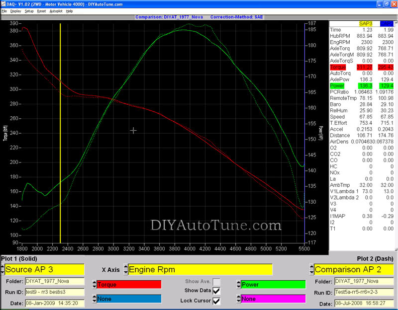
I put the car on our in-shop dyno and dialed it in. Compared to the factory Quadrajet and cast-iron intake this car makes much more torque and upper-end horsepower now than it did, but I now need to tell you a bit more of the story as I don’t have a comparable dyno plot from the Quadrajet/stock intake. Before I converted to EFI I tested a couple different intake manifolds and tried a brand new Holley 600 carb as well. Not suprisingly I found the best combination for this mild 350 was the Edlebrock Performer manifold and Holley 600 carb, where it made 186.9whp peak and 295ft/lbs of tq at 2300rpm. The best I was able to do with this GM TBI, which is a 480cfm 2-barrel by the way, was 184.3whp at peak and 311ft/lbs of tq at 2300rpm. A slight decrease in the top end horsepower, and a decent increase (16 ft/lbs) in low end grunt.
Test5 was the best we did with any Carb/Intake combo. That’s the dotted lines.
Test 9 was the GM TBI, that’s the solid lines. You can see this does great up until about 4000rpms on this mild 350. It then falls off a bit due to lack of airflow, then pulls back ahead at higher RPMs as the AFR (air/flow ratio) with the carb got too rich up here killing power, and we kept the AFR in check with the EFI system. If the carb had been leaned out a bit up top chances are it would have made a bit more power up top than this small TBI did. A bigger TBI though would take that advantage away.
If you want a simple install using a TBI like this but want a higher flow TBI, there are modified hi-flow GM TBI’s available in the aftermarket (ebay is a good place to look), and Holley has a 900CFM 4-barrel TBI that works just great with MegaSquirt, you can often find them used on Ebay or Craigslist. The airflow is the problem, 480cfm just isn’t enough, 900cfm, that would be nice on this motor and give room for a few mods. And unlike a carb you’re not going to have a problem if you go a bit larger than you need, you’ll just have room to grow.
Either way, I’m only out what, $75 on this TBI even after the rebuild even if I decide to upgrade to a bigger unit, or go MPFI (which is what I’m thinking).
Another Dyno Chart you should see for future comparisons
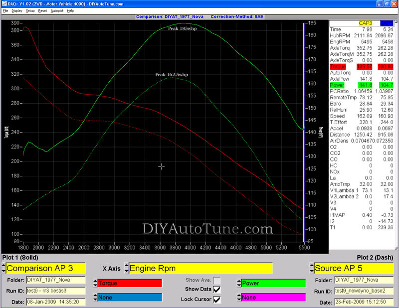
In the middle of this project I had the opportunity to get a new dyno, a much bigger dyno that can handle about 3x the horsepower of the dyno I had been using. I had to jump on it. It’s the same brand (DynaPack) but it’s a 2WD 4000 good for 1100-1200whp. What this means to this test is the dyno graphs I’ve got from the old dyno will not directly compare to this new dyno as it will read differently, they all do. This machine reads a good bit lower than my old machine did, about 14% on this car it seems. I wanted to show a graph of the results from the old dyno, compared to the results as taken on the new dyno for comparison. Keep in mind that the car is in the exact same configuration, I’ve changed nothing at all, not the tune, not any hardware. The only difference between these two plots is the dyno used to take them and the day they were taken on. On future tests in future articles, the new dyno plot here is what we’ll be comparing to as I’ll be continuing to test on this new machine.
You can disregard the funky torque reading right at the beginning of the pulls, that’s the torque converter causing that. It’s not there on the newdyno pull as I started it at a lower RPM and that funkiness is off the chart to the left. You can see though that at peak WHP it’s a 22.5whp difference in the readings from the old dyno to the new. Same car configuration and tuning, just different dyno, different day. My old dyno apparently read a bit higher than a typical DynaPack, and this new one is going to be a bit of a heartbreaker. That’s OK though.
Just keep in mind in future articles related to this car, you’ll be comparing to the lower numbers here to see how we’ve improved from the initial TBI fuel only setup– I wish I had this dyno around when I had the carb setup on it so I could keep all the comparisons consistent, but that’s just how it goes.
Impressions
The car just flat out runs better than it ever has. Fires up on the coldest of GA mornings (mid-high 20’s water temp) with the first turn of the key and warms itself up beautifully just like a new car would. Idles itself up when cold and down when warm. I had a steady idle at 360rpm once, but I tuned it back up to a bit more reasonable speed as I don’t trust it to always be happy idling at that speed under different loads. It’s making within 2-3hp peak of what the best 4-barrel carb I tested did (Holley 600) and this is with a 480cfm 2barrel TBI. In every way the car runs better than ever, but under highway cruise conditions the TBI sitting on the carb manifold doesn’t distribute the air/fuel mixture evenly enough to lean out the mixture too much on this car so I’m running it a bit richer than I’d like, not that different than the carb. As the air/fuel mixture isn’t as even as I’d like to see I can’t lean it out when cruising where it needs to be to get the mileage, so I’m not seeing a big improvement in gas mileage. Only the slightest bit better than the Quadrajet on the stock manifold. Multiport should go far to correct this, and I should also mention my heads are a pretty nasty casting with the ports being pretty horribly mismatched to the intake, many of them about 10% blocked due to the poor casting. I left them this way for consistency in testing, but I know it’s playing a role with fuel puddling and falling out of the airstream. MPFI will certainly help but if this nasty casting is playing a large role that will still get in the way some. After I convert to MPFI and test I’ll be dropping new heads on. Until then I want to leave this factor in place for consistency.
As far as enjoyability and driveability– it’s vastly improved. That’s great for one of the least expensive routes to EFI, and one that can be easily adapted to MPFI if you’d like to later, in fact, that sounds like a good idea for another article. Taking what we’ve got here, a good thing, and showing how, in baby steps, we can make it better.
Parts Used in this Article
This is not a complete list of every little bit part you’ll need, but rather what we offer as well as the major TBI components
Engine Management System
- MegaSquirt-II Engine Management System
- MegaSquirt Relay Board
- MegaSquirt Relay Cable (MSRelayCable)
- Wire Bundle (LG-WireBund)
Fuel System
- Walbro GSL392 255lph Inline Fuel Pump
- Walbro 400-939 Fuel Pump Install Kit (includes brackets, terminals, and barbed fittings, we ended up using some AN fittings like these)
- Fuel Filters (Pre Pump and Post Pump)
Tuning Tools
Throttle Body Injection (TBI) EFI Hardware
- Junkyard TBI unit from 1992 GMC 2500 Van with 350 Motor
- Included injectors, several inches of all attached wiring, and fuel hard lines
- TBI Adapter Plate, Summit Racing Part# TRD-2210
So you want our tuning map?
Sure, why not? But don’t get too excited, you can copy my homework but you’re likely to have to change some of the answers a bit. Here’s a copy of my .msq file, the full configuration of my dyno-tuned map from the above project. It’s not going to be perfect for your car, but if your car is very similar to this test car it might be a good foundation. To be honest, most of you won’t really need this, the base map that comes on the MS2 fired my car up with minimal configuration as I showed in the video above, but I wanted to share this as it may help some of you or inspire a bit of confidence or whatever.
DIY’s Nova Project Fuel Control .MSQ (right click and choose Save As, remember where you save it, then when connected to your ECU you’ll be able to ‘FILE>OPEN’ this file)
Note, this was built on a Small Block 350 Chevy motor from a 76 Monte Carlo (swapped into this Nova). Edlebrock Performer Intake. GM TBI from a 350 Chevy (65lb injectors). Headers into 3″ Exhaust and Flowmasters. Stock heads and cam. This was built, and should only be used on, a MegaSquirt-II with firmware 2.888.
I DO NOT recommend you drop this file on your car and go any more than I would with the base map. Each individual tuner, whether that’s you or a professional, is responsible for making sure the EMS is properly tuned before driving!
What’s coming in future articles?
- More Ignition Control Options — You don’t have to do what we did here though if you’re running a Chevy, this is easy and recommend. We’ll show you some other options though as well that will work on a Chevy or any number of other engines.
- Holley TBI’s, would they help make any more power, breathe more evenly? I have had a generous offer from someone to borrow a 900cfm Holley TBI to test. Results will be documented.
- MPFI Conversion – Holley Stealth Ram system is on order. This will add cost, we’ll find out if it’s worth it and let you know.
Links to all Articles in this Series:
Carb-To-EFI Conversion: One Step at a Time – 1977 Chevy Nova with SBC 350
Part1: GM TBI Fuel Only
Part2: Adding Ignition Control (HEI8)
