Using the stock distributor, wasted spark, or coil on plug

Looking for the easiest way to do this? We now have a MSPNP option, currently available for 1993-1995 models. This ECU comes fully assembled and ready to plug into the stock wiring. See this link for how to install a MSPNP in these cars. To buy an MSPNP for a ’93-’95 Probe or MX6, click here.
Application(s): This article covers the 1993-1997 Ford Probe GT, Mazda MX-6, and Mazda 626 equipped with the KL-DE, KL-03, or KL-ZE engines (2.5 liter V6), with a manual tranmsission, as well as the ’92-94 MX-3 with the 1.8 V6 or one of the above 2.5 V6s swapped in. See notes about automatic transmissions under “Other Things the ECU Controls.” The first generation Probe LX used a 3.0 pushrod V6 with electronics very similar to the 5.0 Mustang, and can be MegaSquirted using the same mods as in our Mustang article.
Level of control: Full Standalone EMS– Fuel and Ignition Control
There have been several ways to install MegaSquirt on these engines, but we’ve worked out a method of using the stock crank trigger wheel and the one tooth wheel in the distributor to get the accuracy of a crank trigger, without having to file any teeth off the pulley or make any other changes to the engine wiring. This works on both OBD-I and OBD-II motors, so if you have a later car, there’s no need to swap in an early distributor.
ECU Modifications
On these engines, you can use any of the current MegaSquirt variants – I, II, or III. We recommend the V3.0 board if building one yourself, or the V3.57 if buying one ready made. The MS3 with MS3X will work out of the box; the MS2 and MS1 require customization. On an MS3, you just have to make sure the jumpers are set correctly. The MS3 can use the stock sensors for sequential injection and sequential coil-on-plug control.
| Using the MS-III PCB V3.0 or V3.57 ECU
And the MS3X expansion board
That’s it! |
If you are using the factory sensors, the MS2/Extra code will support them without any modifications under the hood.
| Using the MS-II PCBv3 or V3.57 ECU
with MS2/Extra 2.0.1 or later code
That’s it! |
Using the MS-I PCBv3 or V3.57 with MS1/Extra firmware
That’s it! |
Wiring
Here are the wires you’ll need to grab for ignition control and where they connect to the MegaSquirt. The crankshaft position sensor is on the front of the block, connected near the temperature sensor. The camshaft position sensor is in the distributor, as is the ignition module. The distributor wiring colors are slightly different depending on the year and model.
Probe wire colors (all years):
| Function | Color | MS1 connection | MS2 V3.0 connection | MS2 V3.57 connection | MS3X connection |
| Crankshaft position signal | Green | Pin 24 (IGN center wire) | Pin 24 (IGN center wire) | Pin 24 (IGN center wire) | Main board Pin 24 (IGN center wire) |
| Crankshaft position return | Blue | Ground (IGN shield) | Ground (IGN shield) | Ground (IGN shield) | Ground (IGN shield) |
| Camshaft position sensor | Blue / Pink | Pin 25 | Pin 3 | DB15 pin 7 | MS3X pin 32 (cam input) |
| Ignition module | Blue / Orange | Pin 36 | Pin 36 | Pin 36 | MS3X pin 14 (Spark A) |
MX-6 1993-1995 wire colors:
| Function | Color | MS1 connection | MS2 V3.0 connection | MS2 V3.57 connection | MS3X connection |
| Crankshaft position signal | Green | Pin 24 (IGN center wire) | Pin 24 (IGN center wire) | Pin 24 (IGN center wire) | Main board Pin 24 (IGN center wire) |
| Crankshaft position return | Blue | Ground (IGN shield) | Ground (IGN shield) | Ground (IGN shield) | Ground (IGN shield) |
| Camshaft position sensor | Pink | Pin 25 | Pin 3 | DB15 pin 7 | MS3X pin 32 (cam input) |
| Ignition module | Yellow / Black | Pin 36 | Pin 36 | Pin 36 | MS3X pin 14 (Spark A) |
MX-6 1996-1997 wire colors:
| Function | Color | MS1 connection | MS2 V3.0 connection | MS2 V3.57 connection | MS3X connection |
| Crankshaft position signal | Green | Pin 24 (IGN center wire) | Pin 24 (IGN center wire) | Pin 24 (IGN center wire) | Main board Pin 24 (IGN center wire) |
| Crankshaft position return | Blue | Ground (IGN shield) | Ground (IGN shield) | Ground (IGN shield) | Ground (IGN shield) |
| Camshaft position sensor | Blue / Orange | Pin 25 | Pin 3 | DB15 pin 7 | MS3X pin 32 (cam input) |
| Ignition module | Yellow / Black | Pin 36 | Pin 36 | Pin 36 | MS3X pin 14 (Spark A) |
MX-3 1992-1994 wire colors:
| Function | Color | MS1 connection | MS2 V3.0 connection | MS2 V3.57 connection | MS3X connection |
| Crankshaft position signal | Blue / Green | Pin 24 (IGN center wire) | Pin 24 (IGN center wire) | Pin 24 (IGN center wire) | Main board Pin 24 (IGN center wire) |
| Crankshaft position return | Blue / Yellow | Ground (IGN shield) | Ground (IGN shield) | Ground (IGN shield) | Ground (IGN shield) |
| Camshaft position sensor | Violet / White | Pin 25 | Pin 3 | DB15 pin 7 | MS3X pin 32 (cam input) |
| Ignition module | Orange | Pin 36 | Pin 36 | Pin 36 | MS3X pin 14 (Spark A) |
Be careful not to wire the crankshaft position sensor backwards; this can result in a noisy RPM signal and unsteady timing.
Idle Air Control
These engines use a pulse width modulated (PWM) idle air control motor. A V3.57 board (or MS3X) can control this directly with no additional mods. With a V3.0 board, you will need to add our PWM idle control mod kit to control this valve.
Other Things the ECU Controls
The stock ECU controls a couple other devices in these cars besides the injectors, ignition, and IAC valve. Here’s what to do about the ones you will need to control.
Fuel pump: This is a standard output on the Megasquirt. Wire the Megasquirt main board pin 37 to the fuel pump relay wire that went to the stock ECU.
Air conditioning: While the stock ECU controls the air conditioner, you don’t need a computer to make this work. Wiring the A/C request wire running to the ECU to the A/C compressor relay should make this work, although we have not tested this one for ourselves. The MS3X can control A/C using one of its on/off inputs and a medium current output.
VRIS: The Variable Resonance Induction System uses two separate solenoids to operate a set of butterflies in the intake manifold to change the intake characteristics. You can leave both open, but it is possible to control them with the MegaSquirt. The factory settings have VRIS valve 1 open at 3250 RPM and valve 2 open at 4250 RPM. You can drive the solenoids from the MegaSquirt using our relay control mod kits, or the MS3X medium current outputs.
Cooling fans: There are two relays for the cooling fans in these cars, one of which turns on the fan in low speed mode and the other turns on the fan in high speed mode. You can either maintain the two stage mode by using one output to turn the low speed fan on and a second output to turn on the high speed fan at a higher temperature, or simply run the fan off at low temperatures and at high speed when the engine gets hot. Use our relay control mod kits for fan control, or the MS3X medium current outputs.
For more information about the relay outputs, see our Common MegaSquirt Modifications page. Note that the MS1 has only four such outputs, and using them all will keep you from being able to also run boost control. With the MS2, there are enough general purpose outputs to run all four VRIS and fan outputs and have one left over.
Automatic transmission: On OBD-II cars, this is controlled by the ECU directly, so if you have a ’96 or later car with an automatic, you’ll need to do a parallel installation. (See this link for more information on how to do this.) On ’95 and earlier cars, the transmission has a separate controller. The transmission relies on signals from the stock ECU. It may be possible to duplicate these signals from a MegaSquirt, but so far we haven’t confirmed what is necessary to do this. The safe bet is to do a parallel installation.
Gauges: These are not controlled by the ECU, so if you’re using the stock distributor you have nothing to worry about here. The MS3X can use its tach output
TunerStudio Configuration for MS3 or MS2/Extra
Set the following under Tach Input / Ignition Settings.
- Spark mode: Toothed Wheel
- Trigger Angle / Offset: 0
- Ignition Input Capture: Rising Edge
- Spark Output: Going Low / Normal for MS2, Going High / Inverted for MS3 It is critical to get the Spark Output Inverted setting correct, as setting this wrong can result in damage to the ignition module or coil.
- Number of coils: Single Coil
- Spark A output pin: D14 (MS2) or MS3X outputs (MS3)
Dwell settings will depend on the coil used; 2.5 to 3.0 msec is a safe starting point. A typical rule of thumb is to back off the dwell until you can just barely detect a misfire under lean cruising conditions, then add 0.2 ms of dwell time.
Use these trigger wheel settings.
- Trigger wheel arrangement: Dual Wheel
- Trigger wheel teeth: 6
- Missing teeth: 0
- Tooth #1 Angle: 60 (this may need to be adjusted slightly due to production tolerances)
- Wheel speed: Crank Wheel
- Second trigger active on: Rising Edge
- and every rotation of: Cam
If you use someone else’s .msq file we do recommend you check the firmware version the .msq file was built on as you cannot always use a file built on one firmware version with an ECU running a different version or a different ignition setup– it’s best to use the .msq files with the same version of the firmware that the file was built on. Alternately you can manually copy the settings over from the borrowed file.
TunerStudio Configuration for MS1/Extra
Under Codebase and Output Functions, set Wheel Decoder to Generic Wheel, and all other code types to Off. Set LED17 (D14) Function to Spark Output A. Do not enable the other spark outputs. Use the following wheel decoder settings:
- Wheel decoder base teeth: 6
- 2nd trigger enable: 2nd trigger
- 2nd trigger active edge: rising and falling
- 2nd trigger and missing teeth: no missing
- Trig Pos A: 1
- Trig Pos B: 3
- Trig Pos C: 5
- Dual dizzy mode: Normal
- Wheel decoder routine: 024s9 style
- Set all unused positions to zero.
On the ‘Spark’ menu choose ‘Spark Settings’ and set ‘Spark Output Inverted’ to NO, and set the trigger angle to 60. It is critical to get the Spark Output Inverted setting correct, as setting this wrong can result in damage to the ignition module or coil. Dwell settings will depend on the coil used; 2.5 to 3.0 msec is a safe starting point. A typical rule of thumb is to back off the dwell until you can just barely detect a misfire under lean cruising conditions, then add 0.2 ms of dwell time.
If you use someone else’s .msq file we do recommend you check the firmware version the .msq file was built on as you cannot always use a file built on one firmware version with an ECU running a different version or a different ignition setup– it’s best to use the .msq files with the same version of the firmware that the file was built on. Alternately you can manually copy the settings over from the borrowed file.
Going distributorless?
Yes, you can use these input mods for a crank triggered distributorless ignition, with different hardware mods. Software changes are minimal: Just enable spark outputs B and C with MS1/Extra, or set Number of Coils to Wasted Spark in MS2/Extra. You will keep the same ignition input mods, but the output mods will be different, and the stock tach will not work without mods as it is triggered from the ignition module. The mods needed will depend on the coils you’re using. For example, these mods will work if using BIP373s to drive a coil without built in ignitors.
The MS3X has no need of mods for distributorless ignition. Instead, you can wire the MS3X spark outputs A through C (wasted spark) or A through F (coil on plug) to an ignition module or coils with built in ignitors, like LS1 coils or our IGN-1A race coils.
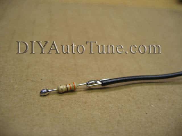
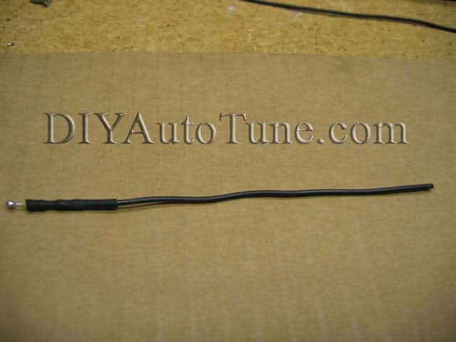
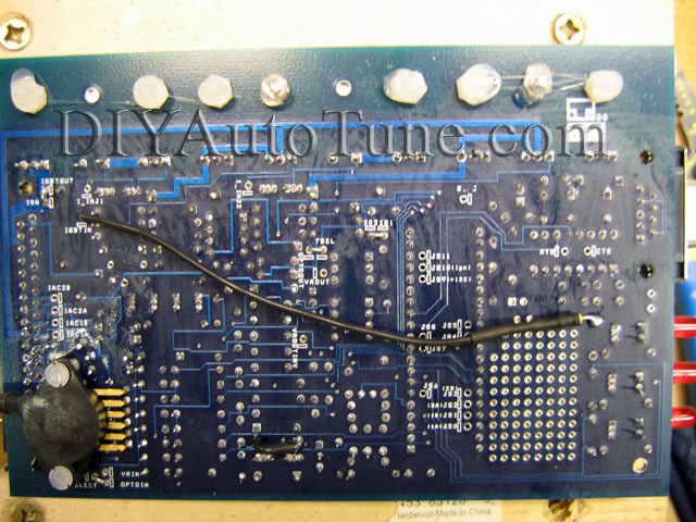
Hardware mods for distributorless ignition (MS1 or MS2):
Now for constructing the outputs…
Enable dwell control and adjust as needed to match the coils you are using. Set the dwell at a very low value to start with (we’ve found Ford EDIS coils have especially short dwell times) and increase it slowly. Back it off if the BIP373s become hot to the touch.
|
Suggested parts
On these motors, you can use a MegaSquirt I or II, although the MegaSquirt-II has the edge. We recommend using a GM open element IAT sensor and removing the air flow meter.
ECU options:
- MegaSquirt-I V3.0 kit
- MegaSquirt-II V3.0 kit
- MegaSquirt-II V3.57 assembled unit
Mod kits discussed in this article:
- MK-BIP373 for wasted spark output – 3 required (not needed for using the stock distributor and ignition module)
- MK-RelayCtrl for fans and VRIS – you may need up to 4 of these
- MK-PWMIAC for idle speed control with a V3.0 board (not needed for a V3.57)
Other recommended parts
- JimStim kit or assembled JimStim
- Stimulator power supply
- 12′ wiring harness or 18″ wiring pigtail
- GM open element IAT sensor
- 3/8″ NPT bung in aluminum or stainless steel
- 6′ DB9 tuning cable
- USB adapter
- Wideband O2 sensor system
Feedback welcome
If you have any further information, contributions, or questions about this article, please contact us.