Why Wideband?
In this week’s Technical Tuesday post, we’re going to walk through bringing a MegaSquirt-equipped vehicle up to date with wideband oxygen sensor control. We’ll talk through some advantages to including a wideband sensor and corresponding controller in your build, as well as some in-depth Tuner Studio setup.
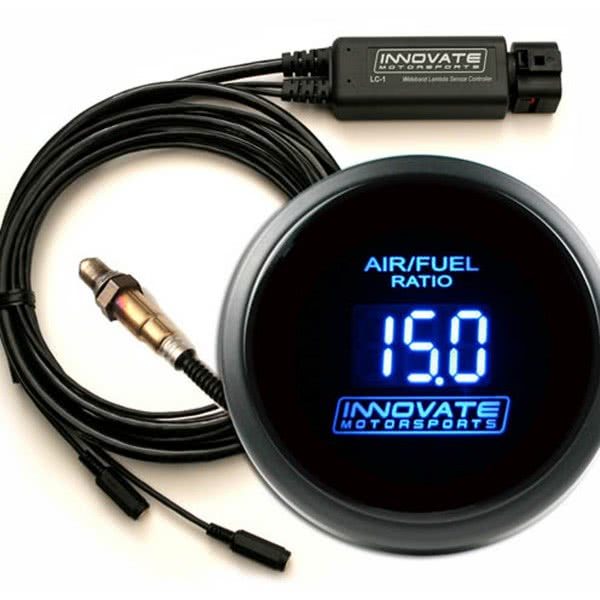
In today’s example, we’re going to be using the Innovate LC-2 controller, gauge, and sensor bundle. This is a great addition to any standalone ECU-equipped vehicle, as the ability to precisely monitor and react to changes in the vehicle’s air-fuel ratio can prove instrumental in getting the maximum performance SAFELY from your combination. While it is entirely possible to run your standalone equipped car without an oxygen sensor at all, the more data we can collect and act on, the better the end result is going to be. Let’s first learn what the difference is between the typical “narrow-band” oxygen sensor and the more advanced wideband family of oxygen sensors.
o2 Sensor Selection
Without going into a long and drawn-out explanation of how oxygen sensors work on a technical level, there are a few things to know. The ultimate goal of the oxygen sensor, regardless of type is to, you guessed it: Sense oxygen. This is important to us because by knowing the amount of oxygen left in the exhaust, we can adjust the amount of fuel we’re using, or even let the ECU do the adjusting to ensure we are achieving the desired AFR ( Air-Fuel Ratio ).
We’ve all likely heard the term “stoichiometric” or “stoich” before referring to air fuel ratios. For gasoline, this number is usually represented as a ratio of 14.7:1 or 1.0 Lambda. This equates to 14 parts of oxygen for every 1 part of fuel. In laboratory conditions, this is considered the ratio for perfect combustion. However, our cars aren’t running around in laboratory conditions, meaning that rarely is our ideal AFR going to be 14.7:1. Different fuel types, rpm and engine load, intake air temperatures, boost levels, etc. can all have a different air-fuel ratio that we would consider ideal.
So, since a narrow band o2 sensor is really only capable of accurately measuring air-fuel ratios from roughly 14.0 to 15.0, we are essentially blind to any ratios leaner ( expressed as above 14.7:1 ), or richer ( below 14.7:1 ). This is because the narrow band sensor typically operates in a range of 0.010 volts to about 0.950 volts, which is fine for part throttle cruise under light loads, or idle in some cases, but becomes nowhere near enough resolution when it’s time to pour on the power.

Wideband oxygen sensors however have the ability to read from less than 1 volt to 5 volts. This, in turn, gives them the ability to sense air-fuel ratios from as low as 10:1 to as high as 20:1. In most cases, we would want to see AFRs in the 12.8 to 13.0 range at maximum horsepower, and a bit leaner in some cases at 13.5 for maximum torque. We can even take advantage of leaning the vehicle out even more in light load cruise conditions up to 15.5:1 or even leaner for maximum fuel efficiency. When dealing with high-performance applications it is often vitally important to know what our AFR is in a wide variety of constantly changing conditions. While every engine may want a slightly different AFR, let’s install and set up our LC-2 to take our tuning to the next level.
What’s in the box?
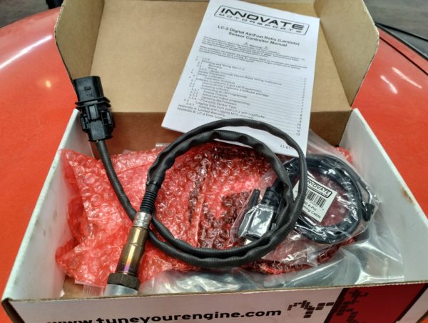
When your LC-2 wideband oxygen sensor kit arrives the first thing we need to do is make sure we’ve got everything we need in the box. You should have the sensor itself, the gauge, the control unit, and the cable to connect the sensor to the controller. You’ll also notice a small harness with a serial cable attachment on one end, and two small connectors on the other. This is to allow programming changes to be made directly to the sensor controller, which we’ll get into a bit later.
Mounting the Oxygen Sensor.
Like all oxygen sensors, we need to find or make a place in the exhaust for our sensor to mount. Ideally what we’re looking for here is someplace where all of the exhaust from either the entire engine (4-cylinder, inline 6 ) or from an entire bank ( engines with a V or flat configuration ). In many cases, the factory oxygen sensor location will likely be easiest to use if applicable to your project. In this case, we’re working on a vehicle with a custom exhaust header going from 6 to 2 to 1, then out. So we decided to place the o2 sensor in the collector after all exhaust runners have been brought together. This allows us to take an average AFR reading from the engine as a whole, rather than just a few cylinders. Another consideration is the sensor angle.
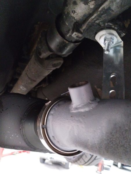
We also want to keep the sensor upright ( wiring harness upward ) as possible. This prevents water vapor condensation, which occurs naturally in the exhaust from collecting in the sensor. This can also help prevent other contaminants (oil, raw fuel, coolant) from collecting in the sensor element as well. Keep in mind, that we need to leave room for installation and removal of the sensor after the exhaust is mounted. Also, make sure the wiring harness is pointing away from any potential problem areas, hot exhaust, driveshafts, underbody components, etc.
Wire it in.
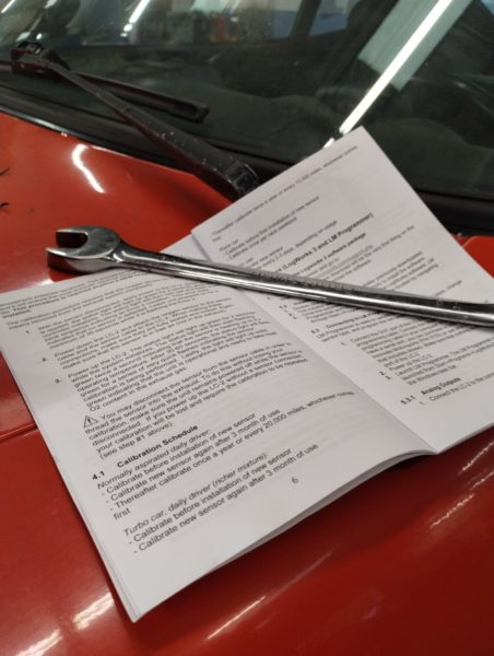
As with any other parts we may be using in our projects, the instruction manual is your best friend! This is where we are going to find installation information, setup processes, and wiring diagrams. There are a couple of ways the Innovate wideband products can be used. We can use just the sensor and controller wired into our standalone ECU. We can use just the sensor and controller with an external gauge. Or like, in this case, we can use the sensor-controller- gauge, AND wire it into the vehicle’s ECU. This way, we can monitor AFR from the vehicle’s cockpit, while the ECU monitors AFR for data logging, target tables, and closed-loop operation.
Be sure to follow all wiring instructions in the manual, including using a relay and fuse for controller power. Grounding, like all of the rest of the electrical components on our racecar, is critical. Be sure to follow the grounding strategies outlined in the manual. I personally like to add connectors when adding components for ease of maintenance or repair later down the line. The “weather pack” style connectors are inexpensive and work well in the engine compartment environment. For higher-end motorsport-level connections, stepping up to a Deutsch DT-style connector can provide a reliable, secure, environmentally sealed connection.
TunerStudio Setup
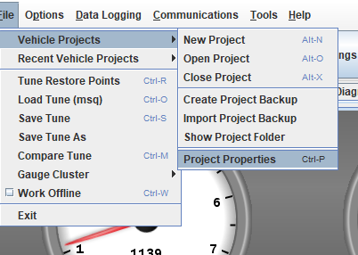
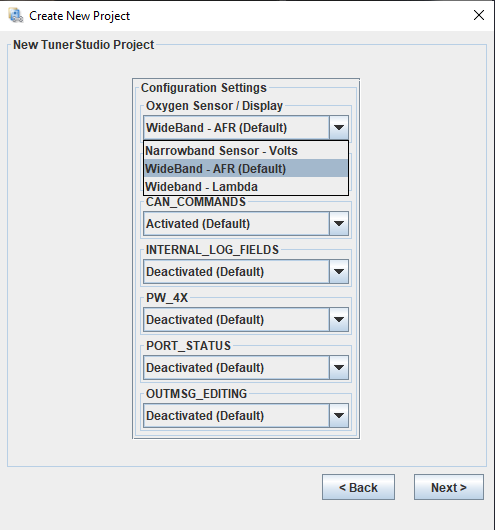
After we have everything mounted and wired in, we need to make a few changes in TunerStudio. These will be to tell the ECU we’re using a wideband sensor. The first change we’ll need to make is in the “Project Properties” section under the “Settings” tab. Here you’ll see “EGO Sensor Selection” and a dropdown menu. There will be a host of wideband oxygen sensor controller options, so choose the one that matches your installation. The important part will be setting the voltage expected to match the output we’re using from our wideband controller. There are two outputs from the Innovate controller, and if we’re using the gauge that will take one of them. The other output can be configured using the LM Programmer software as part of the Innovate LogWorks package. In this case, we need to change the output settings in the wideband controller to 0-5v and set up our EGO Sensor Selection to match the 0-5v expected.
EGO Control
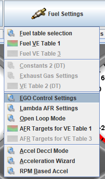
Next, we’ll need to set up the EGO control in our project. Under the “Fuel Settings” tab choose “EGO Control Settings”. This is where we’ll put our new sensor to use! Choose “Wide Band” next to the EGO sensor type. You’ll notice there are a number of settings that become active when wideband is selected. The default settings will be just fine in almost all cases. But, you may want to adjust the RPM and Coolant Temp thresholds as well as the Controller Authority %. This is when the ECU chooses to make fueling adjustments toward your target AFR, and the percentage of fueling change it can make. 15% is generally a good place to start, however, it can be adjusted as necessary.
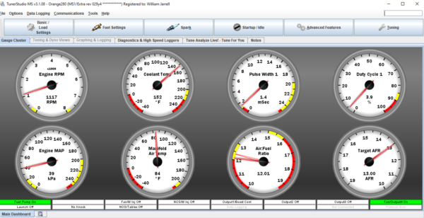
Dashboard Dials
Another great feature of the TunerStudio software is the ability to configure your “dashboard” in any way you’d like. In this example, I wanted to add a gauge displaying the actual AFR as well as one to show our target AFR. This is just a matter of right-clicking on a gauge and selecting from the menus of all available gauge options. Having easy access to this information can be a huge help when tuning, as you can watch in real time what changes need to be made, and how the engine is reacting.