Gain Valuable Data
Using standalone engine management like MS3X offers the flexibility to use additional temp or pressure sensors tailored to your project. This allows for finer tuning and/or more data. While additional I/O is a great feature, many times there can be some confusion in making full use. Today, we’ll explore one of the most common uses for the MS3X’s additional inputs: temperature or pressure sensors. These sensors play a crucial role in monitoring various aspects of the engine. Boost pressure, fuel pressure, cooling system pressure, and more. By understanding how to wire in and configure these sensors, you can gather valuable data to optimize your engine’s performance.
Understanding Two-Wire and Three-Wire Variable Resistance Sensors
MS3X uses two and three-wire variable resistance sensors for temperature and pressure monitoring. Understanding how these sensors work is essential for wiring and configuring them correctly.
Two-Wire Variable Resistance Sensors
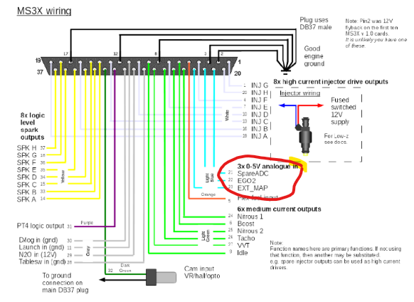
Two-wire variable resistance temperature sensors or thermistors are relatively simple in their design and operation. These sensors consist of a temperature-sensitive element that changes its resistance based on the measured temperature. There are two wires connected to the sensor that serve as supply/signal return and sensor ground path. The ECU measures the voltage drop across the sensor, which varies as the resistance changes, and interprets it as the corresponding temperature or pressure reading. Wiring such sensors to the MS3X board involves connecting the sensor signal wire to a spare ADC input and completing the circuit with the sensor ground wire back to the ECU.
Three-Wire Variable Resistance Sensors
Three-wire variable resistance sensors, on the other hand, incorporate an additional wire compared to their two-wire counterparts. This type of sensor is typically used for measuring pressure. These sensors use a reference voltage wire, a signal wire, and a ground wire. The reference voltage wire supplies a stable 5V reference to the sensor, while the signal wire returns a voltage between 0.5V and 4.5V to the ECU, depending on the measured pressure or temperature. By measuring the voltage on the signal wire, the ECU can determine the corresponding sensor reading. To wire a three-wire sensor with the MS3X system, you can tap into the TPSREF circuit to provide the 5V reference supply, simplifying the wiring process.
Wiring in Temperature and Pressure Sensors
To begin utilizing additional temperature or pressure sensors with the MS3X system, the first step is to wire them correctly. The process differs depending on the type of sensor being used.
Wiring Two-Wire Temperature Sensors
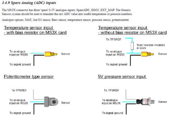
If you’re using a standard two-wire temperature sensor, wiring it to the MS3X board is relatively straightforward. You can follow the guidelines provided in the MS3X Hardware manual. Start by running a wire from one of the three spare ADC inputs on the 3X board, namely “SpareADC,” “EGO2,” or “EXT_MAP,” to the sensor. Then, connect the sensor ground wire back to complete the circuit.
Wiring Three-Wire Pressure Sensors
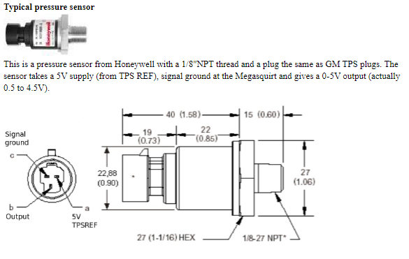
For three-wire pressure sensors, the wiring process involves an additional connection. Sensors transmit pressure changes as a voltage between 0.5V and 4.5V to the ECU using a 5V reference. To supply the sensor with a 5V reference supply, you can splice it into the TPSREF circuit and run a wire to the pressure sensor. It’s important to note that this reference supply can be shared with other 5V referenced components like the TPS sensor or additional MAP sensor, simplifying the wiring process.
One thing to keep in mind with either type of sensor you decide to use, the sensor signal wire CANNOT be shared. You need two sensors if you want the ECU and a separate gauge to display the same temperature. One with the signal wire to the ECU and one to the gauge.
Configuring the ECU for Sensor Inputs
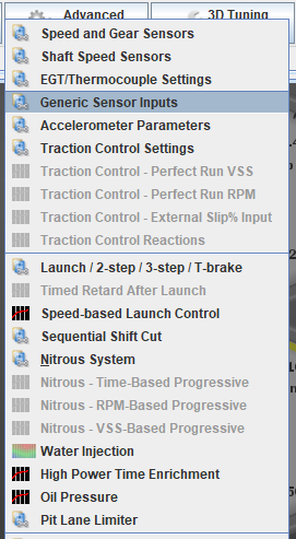
Once the sensor is wired in correctly, the next step is to inform the Engine Control Unit (ECU) where to expect the signal from the sensor. This configuration can be done in the “Generic Sensor Inputs” tab, which can be found under the “Advanced Engine” tab in the MS3X system.
Choosing the Sensor Input and Naming the Field
In the “Generic Sensor Inputs” menu, you have the option to choose the input you’re using for the additional sensor. You can also give it a descriptive name, such as “Intercooler Temp” or “Oil Pressure,” in the “Field Name” box. This helps in organizing and identifying the specific sensor within the ECU settings.
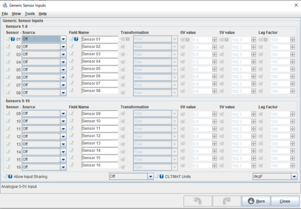
Selecting the Sensor Source and Calibration
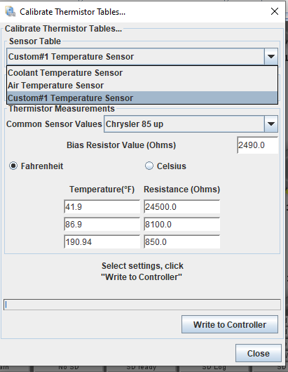
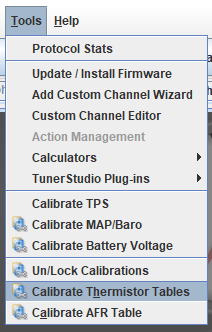
After choosing the input and naming the field, you need to specify the source of the sensor in the “Sensor-Source” menu. Depending on the type of sensor, you may be able to use pre-set calibrations like the “GM Calibration” for air and coolant temperature sensors. However, if you’re using a different type of sensor, you’ll need to determine how the sensor will read based on its resistance. This will tell the ECU what to expect when the signal is low and when it is high. In such cases, you can set up a custom calibration in the “Calibrate Thermistor” menu. Provide the resistance for a given temperature or pressure, and the software will interpolate the values for intermediate temperatures.
Now, you can use these additional temp or pressure sensors for datalogging purposes, have the data displayed on a gauge in TunerStudio or output to your dash if using something like one of the units from DD-EFI or DASH2PRO. More sensor inputs mean more data for changing tables, warning indicators, and power management plans. Stay tuned, as we will delve into this in later blog posts.