If you haven’t already, please read the ‘disclaimer’ at the top of the parent page here.
The mods for using MS2 and MS3 on an RX-7 are a bit more complicated than many, but we’ve been working with Ken Culver to put together a daughterboard that makes this installation a paint by numbers exercise. It does, however, have a bit more numbers than your typical MS installation. This uses the Zeal Engineering Daughterboard, which we’ve tested extensively on several RX-7 test mules. You can find more extensive notes on it at this link. Here, we’ll restate the basics of assembling it, and go over how things specifically work on the RX-7.
The other option is to use an MS3 with MS3X. Rotary support has been a part of the MS3 for a long time; the first car to run production MS3 hardware was an RX-7. The MS3X already has the second VR conditioner and spark outputs already there.
Applications: This covers the FC (second generation) RX-7, as well as first generation RX-7s converted to FC ignitions. We’ll also touch briefly on the FD in this article, though current MegaSquirt firmware does not control the sequential twin turbo setup found on these cars.
Based on our testing, we recommend either the MS2 V3.0 or V3.57, running MS2/Extra firmware 2.1.0 or higher, or an MS3 with MS3X.
ECU Modifications – MS2
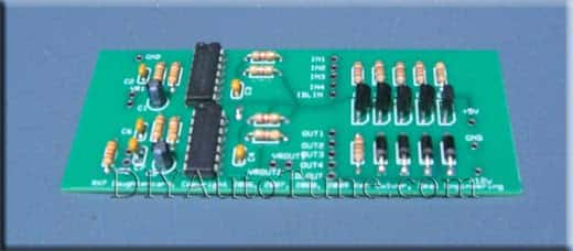
First, we’ll cover how to build a Zeal Engineering Daughterboard. You’ll need to assemble one of these whether you use a V3.0 or a V3.57 board.
Daughterboard Assembly
At this point, you’ll have a complete daughter board, and we’ll assume you are starting from an unmodified MegaSquirt. Here’s how to set up the MegaSquirt for this. |
Now, the instructions split off depending on what board you’re using. The daughter board will go in the case lid.
| Using the MS-II PV3 ECU
with MS2/Extra 2.0.1 or later code
That’s it! |
If starting from a V3.57 board, we’ll assume you are leaving the IAC jumpers in place and use the DB15 connector to add the extra inputs and outputs required to run an RX-7 ignition. These directions start with a standard, off the shelf V3.57 that has not been ordered with any options.
| Using the MS-II V3.57 ECU
with MS2/Extra 2.0.1 or later code
That’s it! |
JimStim testing on an MS2
Testing the Zeal inputs on a JimStim can be tricky (and they won’t respond to a regular Stim at all). The LM1815 will not work with a square wave. You’ll want to use a 12 volt pull up on both the primary and secondary tach signal. For the primary tach signal, you can set the jumper for VR emulation. There is no correspoinding jumper for the secondary tach signal. Instead, put a 0.1 uF capacitor inline between the “2nd Trigger” connection on the JimStim and the VR input on the MegaSquirt. This will give a signal that can trigger the LM1815.
ECU Modifications – MS3
This requires considerably fewer changes:
| Using the MS-III PCB V3.0 or V3.57 ECU
And the MS3X expansion board
That’s it! |
A note on temperature sensors
RX-7s have a somewhat unusual set of temperature sensors with a much higher resistance reading than most. One popular mod is to replace R7 (and R4, if using the stock IAT sensor) with 39K resistors. This gives somewhat more accuracy. Use the Tools -> Calibrate Thermistor Tables in the tuning software to adjust for the different range.
External Ignition Wiring
Here’s how to wire the MegaSquirt up to the stock ignition components. The NE signal corresponds to a crankshaft position sensor signal on a piston engine, while G is equivalent to a camshaft position sensor. These colors are taken at the eccentric shaft position sensor.
| Function | Stock wire color | MS2 V3.0 connection | MS2 V3.57 connection | MS3 / MS3X connection |
| NE + | Red | Pin 24 | DB37 Pin 24 | Main board pin 24 |
| NE – | White | GND (pin 2 on our harness) | GND (pin 2 on our harness) | GND (Main board pin 2 on our harness) |
| G + | Green | Pin 25 | DB15 pin 3 | MS3X pin 32 (Cam input) |
| G – | White w/ black stripe | Pin 27 | DB15 pin 4 | Main board GND |
| Leading coil 12V | Tan | 12 volt switched power | 12 volt switched power | 12 volt switched power |
| Leading coil IGT | Red | Pin 36 | DB15 pin 10 | MS3X pin 14 (Spark A) |
| Leading coil ground | Coil body | Engine GND | Engine GND | Engine GND |
| Trailing coil 12V | Tan (2 wires) | 12 volt switched power | 12 volt switched power | 12 volt switched power |
| Trailing coil IGT | Red | Pin 31 | DB15 pin 11 | MS3X pin 33 (Spark B) |
| Trailing coil select | White | Pin 29 | DB15 pin 12 | MS3X pin 15 (Spark C) |
| IGF | Yellow | Not used by MS | Not used by MS | Not used by MS |
| Trailing coil tach signal | Black | To tach | To tach | To tach |
The black wire on the leading coil is not connected.
For those using a relay board (useful if the stock harness hasn’t held up too well and you’re rewiring the car from scratch, or if you’ve transplanted a FC ignition into a first generation, carbureted car), here’s how this translates into a relay board setup. Note that V3.57 setups do not run very many of the ignition wires through the relay board; they mostly use the DB15 on the ECU instead. Same for MS3s – they run many of the signals through the upper DB37.
| Function | Stock wire color | MS2 V3.0 connection | MS2 V3.57 connection | MS3 / MS3X connection |
| NE + | Red | Relay board tach terminal | Relay board tach terminal | Relay board tach terminal |
| NE – | White | sensor return terminal | sensor return terminal | sensor return terminal |
| G + | Green | S1 | DB15 pin 3 | MS3X pin 32 (Cam input) |
| G – | White w/ black stripe | S2 | DB15 pin 4 | sensor return terminal |
| Leading coil 12V | Tan | 12 volt switched power | 12 volt switched power | 12 volt switched power |
| Leading coil IGT | Red | S5 | DB15 pin 10 | MS3X pin 14 (Spark A) |
| Leading coil ground | Black | Engine GND | Engine GND | Engine GND |
| Trailing coil 12V | Tan (2 wires) | 12 volt switched power | 12 volt switched power | 12 volt switched power |
| Trailing coil IGT | Red | S4 | DB15 pin 11 | MS3X pin 33 (Spark B) |
| Trailing coil select | White | S3 | DB15 pin 12 | MS3X pin 15 (Spark C) |
| IGF | Yellow | Not used by MS | Not used by MS | Not used by MS |
| Trailing coil tach signal | Black | To tach | To tach | To tach |
FD coils are similar, but there’s no trailing coil select output. Instead, you’ll use the output connected to Trailing Coil IGT for the trailing front output, and Trailing Coil Select is replaced by the trailing rear output.
Settings and Configuration
MegaSquirt, for the most part, will treat a 13B engine as a four cylinder (since it has two spark events every rotation of the eccentric shaft) with a 2600 cc displacement (since it draws in 2600 cc of air every two rotations of the eccentric shaft). The most important difference is that the rotary engine has two spark plugs per rotor, and unlike a piston engine with dual plug heads, the plugs don’t fire at the same time. MS2/Extra code allows you to tune the split angle between the spark plugs. Positive split means the leading plug fires before the trailing, while negative split means the trailing fires before the leading. Here are the key ignition settings to use:
- Spark mode: Toothed Wheel
- Trigger angle: 0
- Ignition input capture; Rising Edge
- Spark Output: Going Low (Normal) for MS2, Going High / Inverted with MS3X
- Number of coils: Wasted Spark
- Spark A Output Pin: D14 (MS2) or MS3X (MS3)
- Dwell type: Standard Dwell
- Maximum dwell duration: 3.0
- Trigger wheel arrangement: Dual wheel
- Trigger wheel teeth: 24
- Tooth #1 angle: 0
- Wheel speedL Cam wheel
- Second trigger active on: Rising Edge
- And every rotation of: Crank
- Enable rotary mode: Rotary on
- Output mode: FC mode
- RX8 mode: Disabled
A brief note about the different rotary modes. The FC ignition uses a single timing signal (IGT) for the trailing coil, and second signal, coil select, to identify which rotor to fire. The FD uses separate IGT signals for the front and rear rotors, while the RX8 mode is a coil on plug setup with four separate signals, one for each coil. Using RX8 mode also requires enabling FD mode. Here’s how the spark outputs work for the three different modes in MS2/Extra.
| Spark output | FC mode | FD mode | RX8 mode |
| A | Leading | Leading | Front leading |
| B | Trailing IGT | Front trailing | Front trailing |
| C | Trailing coil select | Rear trailing | Rear trailing |
| D | – | – | Rear leading |
MS3 code uses a somewhat different wiring pattern for the MS3X outputs. This is for 1.4.0 and higher code; some earlier codes used different wiring. This only applies to the MS3X outputs (or on an MS3-Pro); the LED spark outputs use the same pattern as MS2/Extra so as to make it easier when upgrading from MS2 to MS3.
| Spark output | FC mode | FD mode | RX8 mode |
| A | Leading | Leading | Front leading |
| B | Trailing IGT | Not used | Rear leading |
| C | Trailing coil select | Front trailing | Front trailing |
| D | – | Rear trailing | Rear trailing |
Sometimes on a first generation RX-7, it’s easier to control the tach from the ECU than the coils. Wire DB37 pin 3 (for a V3.0 board) or DB15 pin 5 (for a V3.57) to the wire going to the stock tachometer, and set the tach output to JS11. If using our wiring harness, you’ll need to crimp a pin to a length of wire to use pin 3.
Idle Air Control
These engines use a pulse width modulated (PWM) idle air control motor. A V3.57 board can control this directly. With a V3.0 board, you can use the circuit on the daughter board for this.
Other Things the ECU Controls
The stock ECU controls a couple other devices in these cars besides the injectors, ignition, and IAC valve. Here’s what to do about the ones you will need to control.
Fuel pump: This is a standard output on the Megasquirt. Wire the Megasquirt pin 37 to the fuel pump relay wire that went to the stock ECU.
Air conditioning: While the stock ECU controls the air conditioner, you don’t need a computer to make this work. Wiring the A/C request wire running to the ECU to the A/C compressor relay should make this work, although we have not tested this one for ourselves. Note that the MS3X has a built in A/C control option.
Boost: You can use a boost control mod kit (or the MS3X) to control boost on the Turbo II motor.
Fuel pressure regulator: One of the relay control circuits on the daughter board can be used to activate the fuel pressure solenoid while cranking, which can help reduce vapor lock.
Automatic transmission: On S4 cars, the transmission controller does not talk to the ECU. On S5 models, the ECU communicates with the transmission controller, so if you have an S5 or later car with an automatic, you’ll probably need to do a parallel installation. (See this link for more information on how to do this.)
Gauges: These are not controlled by the ECU, so if you’re using the stock ignition you have nothing to worry about here. See notes in the ignition for using the MS to control the tach.
Oil metering pump: S5 RX-7s have a stepper motor driven pump to mix oil with the fuel. The MS firmware does not control this; we recommend removing this system and pre-mixing 2 stroke oil with the fuel in the gas tank. S4 engines used a mechanical system that does not connect to the ECU.
What to Order
If you’re buying an assembled unit, it will need special mods to work with the ignition, as described above. We can install these for you for an extra charge; please contact us for details.
If you’re building an MS2 unit from a kit, here is what we recommend.
MS230-K MegaSquirt II V3.0 Kit
ZealDB1-K Zeal Daughterboard Kit
JimStim-K JimStim kit
MSHarness12 12′ wiring harness
TuneCable6 serial cable
USB-2920 if your computer doesn’t have an adapter port
IATwPiggy Open element IAT sensor – for removing the stock air flow meter
We also recommend a wideband oxygen sensor system for tuning.
Other RX-7 MS articles throughout the Web
There are several other, even more detailed, articles on how to MegaSquirt the RX-7. One of the more in depth ones we’ve found is this one written by Aaron Cake: How to MegaSquirt your 2nd Gen RX-7 – highly recommended for further reading.