NOTE: The DIYPNPB55-K Kit has been discontinued as of 8/30/18.
1987-1988 Porsche 944S USDM 2.5L MT
Test Vehicle Details:
The vehicle used for drawing up these application docs was a USDM 1988 Porsche 944S 2.5L with a manual transmission. All factory electronics/ignition system components are in place and the factory wiring harness is in satisfactory condition. This vehicle is also an E-Production spec race car.
Other notes:
Article details installing the DIYPNP with the AFM in place, as well as deleting the AFM for better intake airflow.
[ARCHIVED] What to buy:
Required:
1- DIYPNPB55-K Kit (DISCONTINUED) This is the main DIYPNP Kit including the Bosch Motronic style 55-pin connector and all components, case, etc.
Optional:
1- Tuning Cable This is the same DB9 serial tuning cable used in other MegaSquirt applications.
1- USB Adapter This is a DB9 serial to USB adapter. The adapter is needed when the laptop or PC you are using does not have a built in DB9 serial port.
1- StimPower This is a power supply that is normally sold to power a stimulator, but another use is it can be plugged directly into the DIYPNP mainboard to power the ECU directly, allowing you to load the basemaps and do limited testing on the ECU prior to installing the ECU in your vehicle. It is particularly nice to be able to flash the firmware and load your configuration on the bench instead of in the vehicle, and allows for less risk of damaging something on the vehicle due to incorrect settings.
1- PNP_IAT-A or PNP_IAT-S AFM/MAF Delete kit. This is a simple kit with an IAT sensor, wire pigtail, crimp pins to poke into the AFM Connector to run the signal back to the ECU, and a steel or aluminum bung (hence the -A and -S in the part numbers). Perfect for getting rid of a restrictive AFM/MAF with your DIYPNP install.
What tools you’ll need: Soldering Iron, Solder, maybe some desoldering braid in case you make a mistake. Small Philips screwdriver. That’s about it.
Startup Maps
Base Configuration .msq files to help you get your car fired up safely and quickly. Ready to tune.
We’re including these maps prior to showing you how to jumper your DIYPNP up. There’s a reason for that. The base ignition settings contained in these maps should be loaded on your DIYPNP before you power your car up (with the key) with the DIYPNP installed. This is to prevent damage to your ignition system in case the default settings are not correct for your vehicle. Note that you can power up the DIYPNP off the vehicle on a power supply connected to the power jack next to the DB15 connector.
So here’s our recommendation — After you complete basic assembly, Power up your DIYPNP one of two ways. Either plug a Stimulator Power Supply into the front panel of the box (the easiest way), or start the Jumper Section below, but only connect the power and ground wires to start with. That way you can plug the DIYPNP into your factory wiring harness and safely power it from your car. The third option, if you’ve fully assembled and jumpered your DIYPNP already, is to unplug your coils from their power connectors before plugging the DIYPNP into your factory harness and powering it from there.
Then and only then, you can flash the firmware on your DIYPNP to the MS2/Extra firmware if you haven’t already, and then load the startup map provided to help you get your vehicle started.
Click Here to Download Startup Maps for this Vehicle
Once the vehicle is started, you will need to use the MS2/Extra manuals to set the base timing and begin to tune the vehicle! This is critical! Do not drive an untuned vehicle!
DIYPNP Jumper Configuration
This section will cover the standard, basic jumper configuration required to get the vehicle running using your DIYPNP.
Vehicle Information
| Market: | USDM |
| Make: | Porsche |
| Model: | 944S |
| Year: | 1988 |
| Engine: | 2.5L 4cyl |
| Transmission: | Manual |
| Trim: |
System Information
| Main Board: | DIYPNP v1.5 |
| Minimum Code Version | MS2Extra 3.0.3 r |
Edge Pin Connections
| Main | Adapter |
|---|---|
| IAT | 44 |
| CLT | 45 |
| TPS SIG | 1K * GND* |
| O2 SENSOR | 28 |
| VR IN + | 48 *** |
| VR IN – | 47 |
| OPTO IN + | |
| OPTO IN – | |
| VR2 IN + | |
| IAC | 4 |
| TACH OUT | ? |
| FUEL PUMP | 3 |
| INJ1 | 17 ** |
| INJ2 | 17 ** |
| 12V | 37 |
| 12V | |
| 12V | |
| VREF | |
| 5V | |
| SG | 26 |
| SG | |
| GND | 2, 42 |
| GND | 10 |
| GND | 14 |
| GND | 19 |
| GND | 24 |
| IGN1 | 1 |
| IGN2 | |
| WLED | |
| ALED |
Pull Ups
| Connection | Resistance | Voltage |
|---|---|---|
| ALED | ||
| WLED | ||
| OPTO+ | ||
| VR2 | ||
| IAC | Flyback Diode | Banded end to 12V |
High Current Drivers
| Output | Enabled | To Pin |
|---|---|---|
| S1 | ||
| S2 | ||
| S3 | ||
| S4 |
Knock Circuit
| Enabled | Sensor + | Sensor – |
|---|---|---|
I/O Circuits
| Circuit | Input From | Out Pin To | Purpose |
|---|---|---|---|
| Relay 1 | |||
| Relay 2 | |||
| Boost | |||
| Input 1 | |||
| Input 2 |
Miscellaneous Jumpers
| On | Off | |
|---|---|---|
| OPTO GND | X | |
| BL/TH | X |
Notes
* Connect TPS SIG to ground with a 1k resistor.** Use one 3.3 Ohm 10 watt resistor per injector bank, connect each resistor output to pin # 17.
*** Use a 25k Ohm resistor in series with VR+ input. Can be in jumper wire or proto area.
Ignition Settings
| Spark Mode | Toothed Wheel |
| Trigger Angle | 0 |
| Main/Return | |
| Oddfire Angle | |
| GM HEI/DIS | |
| Use Cam Signal | |
| Ignition Input Capture | Rising Edge |
| Spark Output | Going High (Inverted) |
| Number of Coils | Single Coil |
| Dwell type | Standard Dwell |
| Cranking Dwell | 6 |
| Cranking Advance | 12 |
| Maximum Dwell | 3.2 |
| Maximum Spark Duration | 1.5 |
| Trigger wheel arrangement | Single with Missing |
| Trigger wheel teeth | 60 |
| Missing teeth | 2 |
| Tooth #1 angle | 110 |
| Wheel speed | Crank Wheel |
| Second trigger active on | |
| and every rotation of |
Other Changes/Considerations
This section will cover changes that need to be made to the DIYPNP that go beyond the standard I/O jumpering, such as intake valve butterfly activation, on/off VVT activation, or other customizations to address the specific needs of a vehicle.
Low Impedance Fuel Injectors
The MicroSquirt Module based DIYPNP will control two low impedance injectors normally (without the Sequential mod allowing for four), or a large number of high-impedance injectors. This vehicle uses four low-impedance injectors and as such you can do one of two things. You can add the sequential module and wire the injectors sequentially (a bit of wiring required). Or you can stay plug-n-play and add resistors inline with the injectors. You will need to use two resistors of about 3.0-3.6 Ohms and rated at 10-20w each. Put one resistor in series with each of the two injector outputs and from each resistor back to connectorboard pin 17. You may mount these resistors inside the DIYPNP case if you’d like. We found some ceramic 3.3ohm 10w resistors at Fry’s that fit nicely.
-
If you are controlling the injectors as the stock ECU does in batch fire, you will need to make sure you set your injector staging to “simultaneous” in the engine constants screen of the tuning software.
VR Sensor Input
To maintain a consistent tach signal to the DIYPNP a 25k Ohm resistor is needed in series with the VR+ input. The VR sensor must also be wired in reverse of how it is wired to the factory ECU. There are two easy ways to accomplish this.
(1) Solder the resistor into the jumper wire from the Connector Board Pin 48 to “VR IN +” on the Main Board.
or
(2) Jumper into and out of the Proto Area. Please view the Proto Area documentation here. Use the jumper wire and solder between Connector Board Pin 48 and one of the outer holes in either Proto Area. Cross over the center section with the 25k Ohm resistor being sure to stay in the same Proto row. Finally jumper from the opposite outer Proto Area hole to “VR IN +” on the Main Board.
Note — the whole goal here is to make sure the VR Sensor + signal passes –through– this 25K resistor before going to the VR IN + hole on the mainboard.
TPS / Acceleration Enrichments
This model does not have a variable TPS, rather an on/off style. As a result the IAC type will need to be set to “PWM Warmup” as well as the standard Accel Enrichments (not Enhanced) used.
Until a variable TPS is added, TPS SIG from the Main Board will need to be jumpered to Ground with a 1k Ohm resistor to prevent the TPS signal from gradually floating higher and possibly accidentally triggering flood clear mode.
The addition of a variable TPS will allow the use of Closed Loop Idle Control as well as Enhanced Acceleration Enrichments as both of these features look to the TPS signal for feedback.
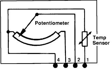
Sensor Calibration
Deleting the AFM (optional) The DIYPNP allows you to disconnect the Air Flow Meter. One thing to note however is when you remove the AFM, the stock IAT sensor comes out with it (the IAT sensor is inside the AFM). You will therefore need to install a GM style intake air temperature sensor in your intake. This sensor connects to the first and forth pins on the IAT connector, as shown in the photos below. IAT sensors have no polarity, so it does not matter which wire you connect to which pin. IAT Sensor:Simply wire a GM Open Element IAT Sensor into your factory wiring harness at the AFM connector. You can poke wires into the AFM connector, or you can cut and splice. Wire one lead of the GM Sensor to the first wire at the AFM Connector, and the other lead of the GM Sensor to the fourth wire at the AFM Connector. There are 5 wire slots in the AFM connector, however only 4 have terminals installed. The two outer terminals will be the ones used.
The wires should then be folded down over the edge of the AFM connector, and the whole assembly firmly and cleanly wrapped in high quality electrical tape sealing it up. 3M makes some good stuff that can handle the temps found in engine bays– read the specs. Read the Manuals, You are Responsible for your own results! This Application Doc is intended to assist you in your DIYPNP DIY EFI Installation. We’ve done a fair amount of research, and actually tested on a similar vehicle to help ensure we can provide the most accurate information possible to make your installation go as smoothly as possible. That said, there are certain things you could do incorrectly, or certain things you could change up, that could cause you to run into issues. Our tech support department will be glad to assist you working through any issues you might have, please contact us and give us that opportunity and we should be able to work things out for you. Startup Maps included/attached to this Application Doc is intended only to help you get your engine started so that you can properly tune your engine. The map will be setup properly for a stock vehicle matching the year/make/model/trim in the ‘Test Vehicle Details’ section at the top of this page. If you have made any changes to your wiring, your ignition system, or other related components, this map may not be ideal for your vehicle. You will then need to check and confirm the appropriate settings and properly configure your DIYPNP EMS for your altered vehicle. Some maps offered may be more completely tuned that others, some may be just setup enough to get the car to fire up and idle with a little help from the throttle. That’s when the tuning begins. In short– We’ve provided you with the building blocks for an incredible EMS. You are however responsible for the implementation and your own successes or lack thereof, but rest assured that we’re here for you and we’re going to do everything in our power to make sure your project is a success. For more information on configuring and tuning your DIYPNP EMS, and for information on adding and tuning custom MS2/Extra features, read up at https://www.msextra.com/ms2extra/. In fact, everyone implementing this system should read that manual from front to back if you really want to harness the power of the DIYPNP EMS. We’d love to hear your feedback on our DIYPNP Application Docs. Click Here to offer feedback/suggestions! |