Greg Banish, Calibrated Success

Our gasoline (and ethanol flex fuel!) engines rely heavily upon their ignition system for proper operation. The process of making power begins with the spark inside the cylinder lighting off a chain reaction between fuel and air molecules that releases heat and increases cylinder pressure well beyond the normal compression work from the piston on the way up. Making sure we can consistently deliver these events starts with ignition energy. It’s this ignition energy that creates a spark across the gap of the plug’s electrodes that creates the flame kernel that will grow and spread across the entire cylinder as combustion begins. Theoretically, the bigger the initial spark, with a hotter arc, the more individual molecules are instantly lit off inside the combustion chamber. This leads to a faster reaction rate on the whole for the combustion process, with hopefully a more complete burn. This is good for power, fuel economy, and emissions alike. In fact, a shorter total burn duration means that we can run less ignition advance and still have the cylinder pressure peak somewhere close to the ideal location (approximately 12-15° ATDC) so we have the best mechanical advantage on the crankshaft through the power stroke.
Since our ignition timing is almost always measured in degrees BTDC, any combustion happening before TDC is effectively trying to push against the normal rotation of the crankshaft. That’s OK because there is so much extra pressure available in the power stroke afterwards that we willingly pay this tax in order to release more total energy. But if we really want to improve overall engine efficiency reducing this loss will certainly help if we can still have good working pressure after TDC. Basically, the bigger the initial spark and flame kernel we can get, the more efficient we can make the rest of the following combustion process. If this sounds too good to be true, you may want a second opinion just like I did. Fortunately, I had the rare opportunity to sit in a class with Dr. Heywood who ran the Sloan lab at MIT and wrote the textbook that many engineers like myself had learned from in college. After class, I asked him directly “Is there any downside to having a stronger ignition system?” In typical engineering professor fashion, I was given a plain response, “NO.” The reality is that from a combustion engineer’s view, we simply cannot have too much ignition energy. It’s the bean counters and packaging engineers who usually tie our hands. Knowing that, let’s move on to delivering spark.
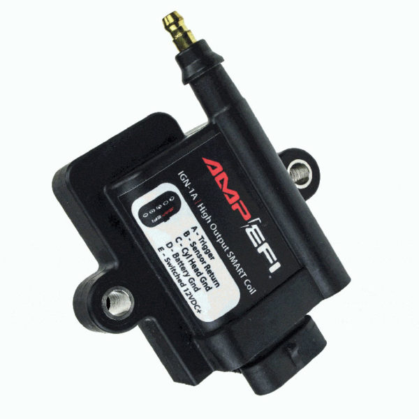
In order to have a spark begin burning the air and fuel inside the cylinder, several things must happen. First, we must convert our relatively low system voltage (12-14v) into something strong enough to jump across the plug gap. The voltage needed to do this reliably is in the thousands, so some form of coil transformer is needed to step up the voltage. By changing the ratio of windings on each side of the coil, we can effectively magnify the voltage by charging the primary side of the coil with system voltage. This results in a secondary voltage with enough potential to arc across a very resistive plug gap (in the presence of compressed air and fuel). As Hot Rodders, many of us know that we must also pick a reasonable gap size for our spark plugs so that this can happen reliably every time under full power, or we risk misfires and a huge loss of power.
For a given ignition energy and spark plug design, we are forced to find a gap that works in worst case conditions (maximum cylinder filling) even though we would really like a bigger flame kernel to kick everything off. Some combustion is definitely better than none, so forced induction applications may see gaps in the 0.020”-0.035” range where the same engine in naturally aspirated trim may run fine with 0.050” or more plug gap.
Put another way, for a given engine hardware and spark plug combination, the more ignition energy we can muster, the more plug gap we can run. This increases the size of the initial flame kernel and speeds up the combustion process, improving efficiency and increasing power. Being forced to run only 0.018” plug gap usually means we have either the wrong spark plug for our engine or just not enough ignition energy being delivered to it.
One more reason we may need additional ignition energy is EGR dilution of the cylinder charge. Exhaust gases can be very resistive to a spark arc attempting to jump the plug gap. As we introduce more EGR into the cylinder, we need more ignition energy to ensure combustion. It doesn’t matter if this EGR came through an external valve or if it was the result of residual EGR from the high overlap of a larger cam.
“Hot and Fresh Out the Kitchen”
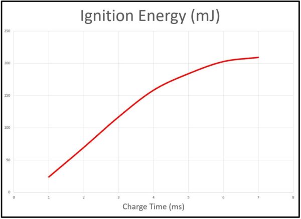
All ignition coils operate on the same principle based upon Faraday’s law of induction. Without diving too deep into the math, it states that the output energy (to the spark plug) is a function of input energy over time. If we do not charge the primary side of the coil very long, we will not get the full potential of output energy from that coil. We must charge the coil long enough (dwell time) to build sufficient energy. This can take 4ms or longer on older coil designs. Newer coils are more efficient and can be fully saturated in as little as 1.5 milliseconds.
Once we have ignition energy available, it must be delivered to each individual spark plug on the engine at the precise time within that cylinder’s operating cycle to begin the combustion process. A mechanical distributor turned by the engine at camshaft speed (1/2 of engine RPM) cleanly solves this need if the plug wires are connected in the proper firing order. As the rotor spins inside the cap, it will intermittently encounter tabs on the cap that connect the coil’s secondary side to each spark plug during the ignition window of that cylinder’s cycle. It is then up to the “brains” of the ignition system to trip the coil into firing at the right time by interrupting primary current and allowing the field to collapse with a spark across the plug gap. Older vehicles used contact points inside the distributor to connect and interrupt the primary voltage to the coil, effectively setting the dwell time of coil charging before each ignition event. Modern ECUs either do this internally or send a signal to an external igniter connected to (or inside of) the coil.
Running a single coil to a distributor does give us a way to deliver spark to all cylinders, but it comes with some additional concerns. First is the obvious addition of a series of critical high-voltage wires that must traverse the engine bay. If any of these connections are compromised, the wires themselves are damaged, or their insulation is abraded/burned, we usually lose operation of the corresponding cylinder. Even in a perfect working setup, the length of plug wires comes with some electrical resistance and voltage drop.
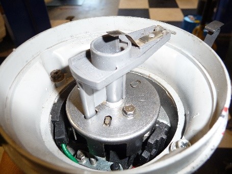
This means that some of that coil energy is lost on the way to the plug. Additionally, high current can also sometimes lead to induced noise in other nearby wires. This has been known to cause issues with radio reception, ECU operation, or other electrical systems if not properly addressed. Perhaps the most limiting factor of running a single coil and distributor is that this one coil must charge and discharge between every single cylinder firing event on the engine. At 6000rpm, the engine completes its full two rotation cycle every 20ms. This leaves only 2.5ms to charge and discharge the coil between events on a V-8.
Multiple coils
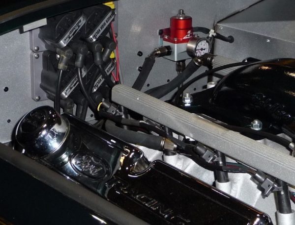
In the search for increased performance and emissions capability, automakers finally took a closer look at their ignition systems. They quickly realized that adding ignition energy would be key to improving the quality of combustion. Doing so would require that the coils be allowed to reach saturation before firing even though the time window stays the same. The solution was more coils. Instead of just one coil feeding a mechanical distributor, multiple coils would feed fewer cylinders each. In most cases, a single coil was used to run two cylinders. The cylinders were chosen as the two whose position in the firing order was 360 crankshaft degrees apart. If the coil was triggered to fire once every revolution, it would hit one cylinder right before TDC of its power stroke and the other at the tail end of the exhaust stroke. Hitting the spark plug toward the end of the exhaust stroke has no significant effect upon combustion because most of that already happened earlier in the cycle.
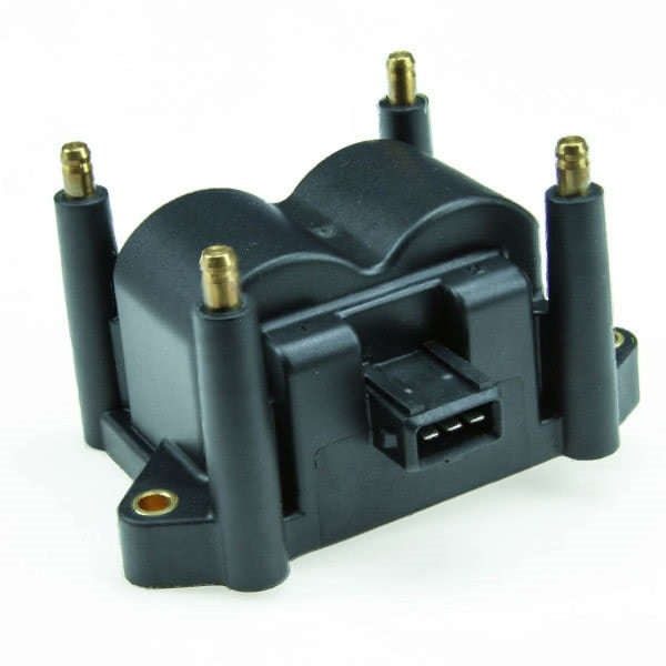
This is where the term “waste spark” came from as the extra event doesn’t really accomplish much other than a tiny bit of additional plug electrode wear. The good news was that the coil now had a full 360° of engine revolution time to charge if needed. At 6000rpm, this opened the charge window from 2.5ms up to 10ms, allowing for more energy. Synchronizing the timing of spark events to piston position on each cylinder now falls to an ECU that must have its own crankshaft position sensor. Note that in this case, a camshaft position sensor is not necessarily needed for ignition control because the coils are being activated once every revolution instead of every other with the addition of the wasted spark event. Remember that sequential fuel delivery would still require a cam position sensor to time the injectors unless batch fuel delivery is also selected.
The next logical progression was to put one coil on each cylinder in what we now call “coil on plug” (Ford Coyote) or “coil near plug” (GM LSx and LTx) systems. If any plug wires are needed, they can be relatively short when the coil is placed in close proximity to the spark plug. If packaging becomes a concern for the coil near a hot exhaust, it can still use a little longer plug wire to relocate. The usual plug wire concerns above still apply here, but at least each spark plug has the undivided energy of a single coil available to feed it. Keeping individual plug wires short or placing the coil right on top of the spark plug reduces electrical transmission losses between the coil and plug.
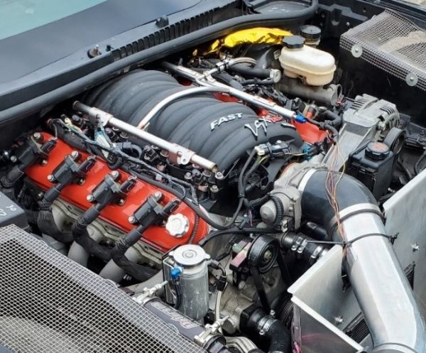
If packaging becomes a concern for the coil near a hot exhaust, it can still use a little longer plug wire to relocate. The usual plug wire concerns above still apply here, but at least each spark plug has the undivided energy of a single coil available to feed it. Keeping individual plug wires short or placing the coil right on top of the spark plug reduces electrical transmission losses between the coil and plug. Following our earlier math, we also see another increase in the available charge window when feeding only one cylinder from each coil. At 6000rpm, we now have the full 20ms available to charge and discharge the coil if needed. While modern coils just don’t need that long to charge, it’s still nice to have.
So why can’t we just increase the dwell time to get more energy?
Good question. The answer lies more in the supporting electronics than the coils themselves. Years of engineering school classes eventually taught me a simple concept: “current equals heat for electronics.” The more current we try to pump through an electronic device (or wire), the more heat it picks up. While the coils are relatively large, they are controlled by tiny IGBTs (Insulated Gate Bipolar Transistors) that can be damaged by too much heat. This heat comes from continuous flow of current during the dwell time. In order to keep the electronics happy, we must have a practical limit to dwell time to give them enough time to cool between events. Although the IGBTs may reside either inside the ECU, in another module, or within part of the coil assembly itself, the temperature concern remains the same.
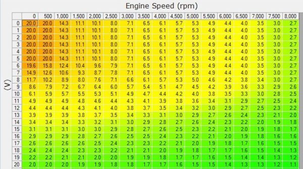
This is why manufacturers often tell us the limit for either raw dwell time (at a rated RPM) or duty cycle. If we cook the electronics, spark delivery goes to zero. I think we can agree that’s bad, right? To avoid this, the base dwell table is usually populated with these limit values at high RPM
One More Variable
We are using system voltage to power the primary side of the coil. While this is usually ~14v with our alternator running, we still have cases where voltage may change. We don’t want a change in voltage to result in either not getting enough ignition energy at the plug or putting too much heat into the IGBTs. To correct for this, the ECU will have a table to adjust dwell versus voltage. This should end up looking much like our injector offset table for many of the same electrical reasons.
Looking back at the differences between the ignition systems, we can see that going from a single coil and distributor toward coil on plug systems allows more time for the coil to recover and cool between events. This greatly increases durability and allows us to make sure that we get our coils up to saturation every time to increase the available ignition energy.

