Greg Banish, Calibrated Success

Idle tuning and control often seems to be an afterthought on some tuning projects. The devil’s work, it seems. Worse some try to do it too soon without nailing other important aspects of the calibration and get hellish results, only to curse the controller.
Proper idle tuning and control can be tricky, and yet, I have worked on a lot of projects where we made it look all too easy. How is that? My answer is rather simple, with a structured approach. Idle control is just one part of my larger tuning process that remains pretty much the same regardless of what engine or ECU I am working on at the time. I essentially use the same approach for both OEM controllers running the latest direct injection and torque-based controls as I do on aftermarket standalone EFI systems like the MSPNP and MS3Pro systems.
Modern OEM controllers today use a complex series of logic to carefully balance idle speed on the fly. These systems are estimating the engine torque, frictional losses, accessory loads, transmission loads and other speed gradients in real time in order to strike a delicate balance to target the desired idle RPM. As an engineer, I love this because I can see each individual component of the total calculation and make adjustments to them individually as conditions change. When I was working on torque control as an OEM calibrator at Ford, I was in charge of tables that estimated the change in alternator torque (corrected for pulley ratio to the crank) as we adjusted field duty cycle to maintain the target system voltage. We had similar tables for torque vs water pump flow too. Everything was accounted for in its own table, and I had them all at my fingertips in the laptop even though consumers would never see them.
On the other end of the spectrum, we have the simplest of aftermarket controllers that merely adjust IAC (idle air control) valve position with coolant temperature and hope that some average AFR control and base spark table are enough to balance somewhere near a normal idle speed. (This was MS2 logic still used in some of the legacy plug and play ECUs, and one of the reasons I really like the upgrade to MS3 and beyond) But even with these systems, there are a few tricks we can play to improve our idle tuning / control. For this article, we’ll focus on the standalone controllers that do a great job their intended task: running non-emissions vehicles with easy-to-use controls.
It’s All About Balance

Whenever I teach a live calibration class, idle control and idle tuning becomes one of the more animated discussions as I take the form of a human scale with my arms outstretched. On one arm I hold the imaginary sum of all forces attempting to slow the crankshaft, engine friction, transmission/convertor drag, accessory loads (including the supercharger), etc. On the other, I have the raw input of combustion forces trying to exactly offset the losses. I show that we must try to make just enough combustion force to exactly equal the forces attempting to slow the crankshaft if I am to hold a stable speed. If the combustion forces outweigh the frictional losses, speed goes up. Conversely, if there is a sudden addition to the losses (A/C compressor kicks on, trans pulled into gear, etc.) without any compensation from input forces/torque, the engine slows down and might even stall. Balancing these positive and negative torques is what the new OEM ECUs do so well with their layers of models for each component.
My First Requirement for Tuning Idle Control
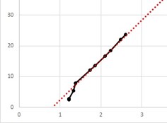
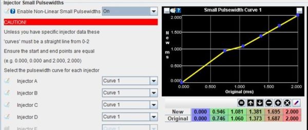
Without exception, I must first be able to demonstrate consistent AFR (Air-Fuel Ratio) control before I can attempt idle speed control. This means that the injector values MUST be accurate all the way down to the smallest pulsewidth I will run. Getting this data means I have either bought injectors from a supplier who has this complete data, or I have run them myself on my Calibrated Success Fuel Injector Bench. Luckily, the MS3 software has a table in it that specifically addresses the non-linear behavior of some injectors at very short pulses and will correct to make sure you deliver the right amount of fuel if it’s calibrated correctly to match your injectors’ behavior. The values that get entered in this table come from calculations based on offline measurements of the injector flow, NOT from poking at them on a running engine if you want them right.
Once the injectors are properly characterized in the ECU, we can focus on the airflow model. This usually means polishing the VE table. Smart calibrators will set up their primary VE table with more breakpoints at lower RPM because engines tend to have more inflection points to the VE at low speed vs high speed as the intake and cam come in and out of various resonances. This may require only a couple hundred RPM between breakpoints in some regions, depending upon the engine. Up top, things get more predictable, so RPM breakpoints might be only every 1000rpm or so. If you’ve done it right, the VE surface will be smooth and progressive when viewed in 3D instead of looking like a mountain range. Also, the VE should be increasing with MAP in every column of RPM, no exceptions. If you think it is lean on tip-in, that’s another article on transient fueling vs steady state mapping. Don’t screw up the VE surface, especially down low. If the VE surface is not correct in steady state for all points in question, we will have a really hard time tuning the idle for good idle control.
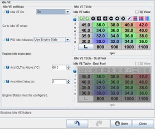
Another really cool feature of the MS3 controls is the Idle VE table. (Found at the bottom of the list under the “Startup/Idle” button) This allows it to switch over to a small, higher resolution VE surface when idle conditions have been met. This table may have breakpoints every 100rpm instead 200rpm, yielding a more precise VE estimate down low, even if actual RPM drifts a little bit. I like to use this to help make sure VE error does not lead to changes in AFR at idle.
Changes in AFR result in changes in torque produced by combustion. Although the change is subtle near stoichiometry (λ=1.0, or ~14.6:1 for pure gasoline), going too far either side of this can either increase (rich) or decrease (lean) the indicated torque being added to the crankshaft. Since I don’t want too many competing forces in play at any given time, I prefer to keep the AFR right near λ=1.0 (with 1-2% wiggle room for closed loop toggling) at idle. This means that the AFR should not be influencing idle speed because its contribution to torque is stable. Now I can concentrate on the real idle tuning / control coming from airflow and spark.
Fast Path, Slow Path
Since we cannot control the comings and goings of negative torques acting upon the crankshaft, we must have a method to react to them in order to maintain our balance. With AFR under control near λ=1.0, this leaves two remaining knobs that can be turned.
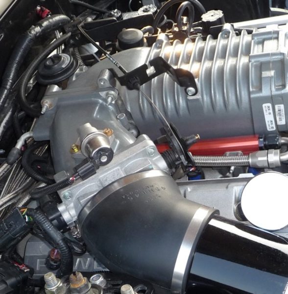
Airflow is the big knob. It moves slow, but it has a lot of authority. The more air (and fuel) we allow into the cylinders, the bigger the bang pushing on the piston and more positive indicated torque the engine makes. Since the total amount of airflow required at idle is small, we can achieve this flow with a closed throttle body and a small controlled leak through the IAC (idle air control) valve. Modern ECUs just bake this function into drive-by-wire logic controlling the blade very precisely below 10% instead of using the outside IAC valve. Small changes in flow area through the IAC have a predictable effect upon air delivered to each cylinder event after the intake volume changes pressure a little. It is this phenomenon of needing to fill the intake volume with more air mass, raising MAP (Manifold Absolute Pressure) slightly first before the extra air makes it to the cylinders, that takes a little extra time and makes it our “slow path” for idle control. This time is usually a couple revolutions of the engine, but if we are worried about an imminent stall, it can be to slow to save us.

Our other control knob in this case is spark advance. We know from WOT testing that spark advance has a visible effect upon delivered torque, even if airflow and AFR are constant. The same holds true at idle, so we use it to our advantage. At every engine speed and load, there is some amount of spark advance that gives us the most torque. We call this MBT (Max Brake Torque) timing, and it is NOT what we want to use at idle. Instead, we intentionally retard the ignition timing at idle, backing the torque down from our theoretical optimum. This creates a reserve of torque that can be called upon should we need it later to balance incoming losses. Changes to delivered spark advance can be done as quickly as the next cylinder’s TDC event, so spark is our “fast path” for torque control. If we are maintaining an average spark advance below MBT timing, we can react very quickly to a momentary drop in engine speed by advancing spark to bring us back toward the target RPM. This is why you’ll often see a sharp downward offset in the timing table near idle. One nice side benefit here is that if the vehicle has catalytic convertors, this retarded timing at idle will help keep them operating at an effective conversion temperature too.
Be aware that there is an invisible limit to how far the timing can be retarded from MBT and still allow stable engine operation. The further we reduce the timing, the less stable combustion becomes and misfires begin to appear. This imposes a practical limit in many cases. However, if the engine has been fitted with a larger camshaft that has enough overlap to create internal EGR from reversion, MBT will be significantly increased. We must increase even the idle spark values to compensate for this if we want clean combustion.
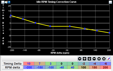
Going a step further, we can also set up corrective timing adjustments based on how far the engine is away from the target idle RPM at any moment in the Idle RPM Timing Correction table. Here, we look at “RPM delta” (Current RPM – Target RPM) and add some amount of timing to our first guess (which was intentionally retarded from MBT) to change the amount of torque being applied to the crankshaft from combustion. Since the RPM is updated so quickly from the crankshaft position sensor, these value can move very quickly as well. When the current speed is below our target idle RPM, the RPM delta is negative and we have the correction table configured to add timing. This moves us closer to MBT again, increasing torque while the losses are still the same. The result is that RPM climbs back toward our target speed in a manner proportional to the spark adjustment in this table. The opposite is true if we have an over-speed condition as timing is further reduced from MBT and we let the frictional losses win for a moment until we get back to our desired RPM.
Engine RPM is never truly stable, as we have alternating power pulses coming and going with friction and other loses that may also be moving. This is what gives us the “lope” with slow idle speeds or big cams. To account for this, I like to give the engine a dead band around zero RPM delta where no correction is made to avoid too much busy-ness of the idle spark control. With bigger cams, this dead band can also be bigger to let them do their thing and sound great.

If you are tuning an ECU that doesn’t have specific idle RPM delta spark correction, it’s still possible to create a similar effect in the base spark table with lower resolution. The trick here is to recognize that MBT usually drops with RPM, so even holding a consistent spark value below the target idle speed has the net effect of advancing the timing relative to MBT. If we add a few degrees of spark advance at a breakpoint below the normal idle speed in the base spark table, we have created a mild form of under-speed control. Likewise, lowering the base spark values at a breakpoint above our target idle speed also reduces torque there and has a tendency to push back toward idle target RPM. The tradeoff here is that if you happen to spend time cruising at 1200RPM, the delivered timing will be pretty soft resulting in slower throttle response and lower fuel economy.
Bringing it all Together
By following these simple rules, we have a much greater chance of creating a robust idle control system that has the flexibility to adapt to a wide range of operating conditions. This can be accomplished without the need for 37 layers of complex OEM controls and a college degree to understand them. There’s no reason your racecar or weekend cruiser can’t enjoy stable idle control just like a new daily driver from showroom. The key is to reduce the number of noise factors when possible (leave fueling close to λ=1.0) and have fast/slow methods of reacting to speed errors just like the OEM guys do. Don’t be scared to use the extra idle tuning and idle control tools in your ECU software, they can make a huge difference in the driving experience.
