Note: The adapter harness kit is discontinued. This page is for reference for people still using this harness.
For the latest in EASY Plug-N-Play Engine Management Solutions for 5.0 Foxbody and SN95 Mustangs check out these products:
Ford Foxbody Mustang 5.0 1986-1993 MS3Pro PNP Plug and Play ECU
Ford Mustang 5.0 1994-1995 SN95 MS3Pro PNP Plug and Play ECU
Ford Mustang FoxBody 5.0 1986-1993 MSPNP Gen2 Plug and Play ECU
Ford Mustang 5.0 SN95 1994-1995 MSPNP Gen2 Plug and Play ECU
If you haven’t already, please read the ‘disclaimer’ at the top of the parent page here.
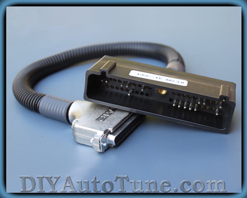
What does this cable do?
Our first set of 5.0 Mustang to MegaSqurt adapter harnesses lets you plug the MegaSquirt into any 1986-1993 5.0 Mustang,. The harness plugs right into the original EEC-IV connector. You will just need to add a MAP sensor line to use Megasquirt’s MAP sensor. You can use the MegaSquirt with your factory temperature and throttle position sensors, and the MegaSquirt can use the factory oxygen sensor if you don’t upgrade to a wideband. A few minor mods are required to the MegaSquirt to use this.
There are two versions of the harness. One is built for the V2.2 board and one for the V3.0 / V3.57. The only difference is the spark output pin, which is on DB37 pin 25 for the V2.2 and pin 36 for the V3.0 / V3.57. At present, we recommend high impedance injectors with this harness until we’ve had a chance to test it with low impedance injectors.
This gives you plug-in control over your fuel, ignition, and the factory idle air control valve. If you’re using an automatic transmission, the transmission will control itself with no ECU input.
We’ve recently added a ’94-’95 adapter harness, too! This one is only available for V3.0 / V3.57 main boards. It does not control A/C or automatic transmissions, but does have the cooling fan outputs for use in an SN95. The cooling fan outputs are on pins 25 (low speed) and 29 (high speed) of the DB37.
Using the Megasquirt-II and EEC-IV Harness with TFI
MegaSquirt-II PCBv3.0 Mods Required:
- Input mod: You install a 2k 1/4w resistor in place of D2. Jumper D1. Jumper TachSelect to OptoIn, XG1 to XG2, and TSEL to OptoOut.
- Output mod: Run a jumper wire from JS10 to IGBTIN and jumper IGBTOUT to IGN. You’ll need to install a BIP373 in the Q16 slot.
- Fast idle mods:
- Remove Q20 and D8.
- Remove R39 and install a jumper in its place.
- Install a TIP120/121/122 in place of Q4. For more information, see our MK-PWMIAC page.
For fan control on a ’94-’95, you can add a pair of relay control mod kits in the proto area, or swap the IAC output wires so you have JS1 wired to IAC1A and JS3 wired to IAC2A. (JS0 and JS2 can be left disconnected).
MegaSquirt-II PCBv3.57 Mods Required:
- Input mod: You install a 2k 1/4w resistor between pins 2 and 3 of the JP1 main board jumper. Put jumper J1 in the 1-2 position, and connect the XG1-XG2 jumper.
- Output mod: Run a jumper wire from JS10 to IGBTIN and install a BIP373 or TIP120 in the Q16 slot.
- No fast idle mod is needed.
- For fan control on a ’94-’95, you can add a pair of relay control mod kits, or swap the IAC output wires so you have JS1 wired to IAC1A and JS3 wired to IAC2A. (JS0 and JS2 can be left disconnected).
TunerStudio Ignition Configuration:
- Trigger offset = 10 degrees (this will vary, depending on the distributor orientation, see below)
- Ignition Input Capture to ‘Falling Edge‘
- Cranking Trigger to ‘Trigger Rise‘
- Coil Charging Scheme to ‘Standard Coil Charging‘
- Spark Output to ‘Going High (Inverted)‘
Then set the dwell setting to 8.0 milliseconds with no battery voltage compensation. This will get the spark output to closely imitate the square wave signal that the EEC-IV computer sends out.
If you are using MS2/Extra, you will use Basic Trigger mode, and a fixed duty dwell with a 50% duty cycle.
More information on setting Trigger Offset:
You must also set the initial position of the trigger (called the ‘trigger offset’), then check it using the Trigger Wizard in TunerStudio (Tools Menu). The trigger offset setting will vary according to your distributor position (where it is in rotation) but you’ll need to set it properly… Basically you use the Trigger Wizard and adjust the ‘trigger offset’ and/or twist your distributor until the advance number in the Trigger Wizard matches what you’re reading with your timing light. The +/- buttons on the trigger wizard will adjust your trigger offset. You’ll need to use these buttons and a timing light to make the number on your light, and the big number on the left in the Trigger Wizard, match up.
Here’s the information on this:
Before tuning your advance table, be sure to use a timing light to verify that your ‘trigger offset‘ is calibrated. Changing the Trigger Offset in TunerStudio will not change the displayed advance, instead, it changes the actual advance as seen with a timing light. Your goal is to make these two match.
To do this, get your engine warmed-up (otherwise the timing moves as the temperature increases) and idling, then use a timing light to verify to be certain your actual advance as shown by a timing light equals your the advance display on the advance gauge in TunerStudio. (8, in this case). (Note that positive numbers denote BTDC, and negative numbers denote after TDC.)
TunerStudio PWM IAC Configuration:
- First open the TunerStudio Configurator, and open CAR1>SETTINGS.INI>SETTINGS>IDLE_CONTROLLER and select PWM_GAUGE from the dropdown box at the top right.
- Save and exit the Configurator.
- Open TunerStudio and connect to the ECU, and from the SETTINGS menu choose IDLE CONTROL.
- Select the PWM Warmup Algorithm’ and then you can configure the values for your vehicle and click Burn to ECU’.
We do not have specific settings for all the Ford vehicles that you may be using this on. For now, information on tuning these settings can be found in the MSExtra Manual.
Coolant (CLT) / Intake (IAT/MAT) Temperature Sensor Calibration
You can use your stock IAT and CLT sensors, and with the MegaSquirt-II you can calibrate these sensors through TunerStudio. It’s best to leave the standard R4 and R7 ‘Bias Resistors’ in place in the MegaSquirt and just configure this in the software. You get better accuracy this way.
- Open TunerStudio>Tools>Calibrate Thermistor Tables
- Select ‘Coolant Temp Sensor’, Select ‘Fahrenheit’, and enter these values:
- Click OK and the Coolant sensor will be calibrated.
- You’re not quite finished yet though— You need to repeat these steps, but choose ‘Air Temperature’ as the sensor table and use the same temp and resistance values from above as the sensors use the same curve. This will calibrate the IAT as well.
NOTE– Make sure you chose Fahrenheit or your readings will be WAY off with the above values….
More Information
- Everyone should thoroughly read the MS2 Manual at MSExtra.com. This is your pride and joy… read the manual and the FAQ!!!
- Read both the MS1 and MS2 sections, not all of the MS1 section will apply to you, but MUCH of it will, and the MS2 section isn’t really complete without this information.
- Another great resource I refer to often is https://www.tunerstudio.com/
A plug and play setup isn’t complete without startup settings. We’ve now posted a 5.0 Mustang base map for you to download, for MS2/Extra 2.1.0 firmware. Here is a brief rundown of the specs on the test car. This map should be a good starting point for a mildly modified 5.0 build. Note that for ’94-’95, you will also need to enable fan control outputs under the Spare Output Port Settings. MegaSquirt-II Base Map
- 1993 5.0 Mustang GT
- Stock short block
- Stock 19 lb/hr injectors
- GT40P (Explorer) head swap
- Edelbrock intake manifold
- Professional Products throttle body
- Shorty headers
- Flowmaster exhaust
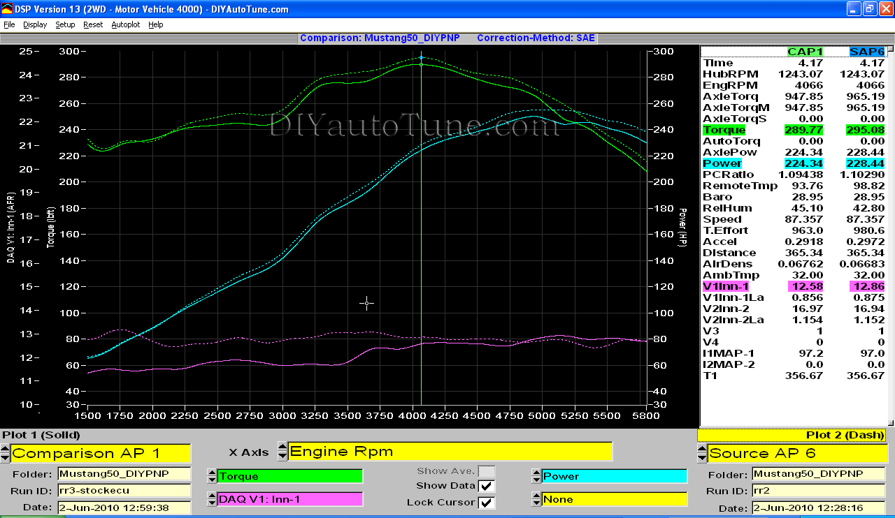
Check out the dyno results – solid line is the stock ECU with the timing bumped up and a MAF piggyback installed, dotted shows how much power we were able to add with the MegaSquirt. Click the picture to zoom in. (Note – this particular screen shot is from a DIYPNP test, but the power with the adapter harness is the same.)
Using the Megasquirt-I and EEC-IV Adapter Harness with TFI
MegaSquirt-I PCBv2.2 Mods Required:
- Input mod: You install a 2k 1/4w resistor in place of D8
- Output mod: Run a jumper wire from the negative lead of LED 17 to pin 36 on the underside of the DB37 connector. On V2.2 boards, there is no hole on the board, so you must solder the jumper directly to the DB37 connector lead.
- Fast idle mod: Replace transistor Q5 with a TIP120/121/122 power Darlington, as shown on our MK-PWMIAC catalog page.
MegaSquirt-I PCBv3.0 Mods Required:
- Input mod: You install a 2k 1/4w resistor in place of D2. Jumper D1. Jumper TachSelect to OptoIn, XG1 to XG2, and TSEL to OptoOut.
- Output mod: Run a jumper wire from the top lead of D14 to the IGN jumper.
- Fast idle mods:
- Remove Q20 and D8.
- Remove R39 and install a jumper in its place.
- Install a TIP120/121/122 in place of Q4. For more information, see our MK-PWMIAC page.
- That’s it!
- For fan control on a ’94-’95, you can add a pair of relay control mod kits in the proto area. Their outputs wire to IAC1A for low speed fan control and IAC2A for high speed fan control.
MegaSquirt-I PCBv3.57 Mods Required:
- Input mod: You install a 2k 1/4w resistor between pins 2 and 3 of the JP1 main board jumper. Put jumper J1 in the 1-2 position, and connect the XG1-XG2 jumper.
- Output mod: Run a jumper wire from PAD1 to the center hole of Q16. Remove R58
- No fast idle mod is needed
- For fan control on a ’94-’95, you can add a pair of relay control mod kits. Their outputs wire to IAC1A for low speed fan control and IAC2A for high speed fan control.
- Set Spark Output Inverted to Yes.
- Set Trigger Angle to 10 degrees.
- Set Dwell to Fixed Duty, and Spark Output Duty Cycle to 50% duty cycle.
- Note: This is for the “Push start” modules, without computer controlled dwell. The computer controlled dwell settings are not fully tested.
This wiring harness uses the O2 sensor on pin 29. To wire up a wideband to it, cut the wire at the EEC-IV connector at pin 29 and connect this wire to the wideband controller’s analog output.