Configuring Megasquirt for a DIYAutoTune.com Crank Trigger
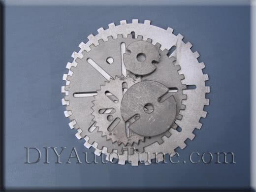
This article covers how to configure Megasquirt for our line of 36-1 trigger wheels. See the main Megasquirt trigger wheel page for more details on the trigger wheels, including how to install them on your car. In this article, we will use the standard orientation described in the installation guide. Here’s how many teeth the gap should be ahead of the VR sensor to use the settings in this article. You’ll notice that the settings for 4, 6, and 8 cylinder engines are the same as the settings on stock Fords.
Number of cylinders
Missing tooth location at TDC
1
9 teeth ahead of the sensor
2
9 teeth ahead of the sensor
4
9 teeth ahead of the sensor
6
6 teeth ahead of the sensor
8
5 teeth ahead of the sensor
12
8 teeth ahead of the sensor
The output mods assume you will be using wasted spark type coils without built in ignition modules. Examples of such coils include Ford EDIS coils, GM 2 tower DIS coils, Dodge Neon or V6 coil packs, or our IGN-4 coil packs. If using coils with built in ignitors such as GM LS1 coils or IGN-1A coils, you will need to change the output circuit.
EDIS on a Megasquirt-I V2.2 Board
Using MSnS-E firmware
Hardware mods required:
Remove D5, D8, R10, and the XG1-XG2 jumper.
Jumper XG1 to the right hole of D5.
Install a 1K resistor in place of D8.
Run a jumper from the bottom hole of R10 and the banded side of the D9 diode.
Use a 750 ohm to 1K resistor to connect the right side of R23 to the negative side of D17.
Run a wire from the negative side of D17 to X11 to bring the SAW output out on the DB37 pin 25.
External wiring:
Connect the EDIS PIP signal to pin 24.
Connect the EDIS SAW signal to pin 25.
Settings required:
Under Codebase and Output Functions:
Set EDIS on, and all other code types off.
Set LED17(D14) Function to Spark Output A.
Turn off all other spark outputs.
Under Spark Settings:
Set Trigger Angle and Trigger Angle Ignition to 0.
If building the board from scratch, you do not need to include D1 or D2, but they do not need to be removed.
Replace R12 with a 1K resistor.
Remove the XG1 to XG2 jumper, and jumper XG1 to TachSelect.
Jumper OPTOUT to TSEL.
Connect a 750 ohm to 1K resistor from the right side of R24 or the 5V hole in the proto area to the negative lead of D14.
Run a wire from the negative lead of D14 to the IGN jumper hole on the opposite side of the board to bring the SAW output out to pin 36 of the DB37 connector.
External wiring:
Connect the EDIS PIP signal to pin 24.
Connect the EDIS SAW signal to pin 36.
Settings required:
Under Codebase and Output Functions:
Set EDIS on, and all other code types off.
Set LED17(D14) Function to Spark Output A.
Turn off all other spark outputs.
Under Spark Settings:
Set Trigger Angle and Trigger Angle Addition to 0.
Distributor Based Ignition on a Megasquirt-I V3.0 Board
Using MSnS-E firmware
Hardware mods required:
Build the VR conditioner circuit. All our preassembled Megasquirts with the V3.0 board come with this circuit installed.
Jumper TachSelect to VRIN.
Jumper TSEL to VROUTINV. (Note: Depending on how your VR sensor is wired up, this can also be jumpered to VROUT. If you are unable to get a signal, you can either switch the jumper or the sensor polarity.)
You may need to adjust the VR trim pots, R52 and R56, when this is installed on a running engine. A usual base setting is to turn them all the way counterclockwise.
Jumper IGBTOUT to IGN to send to IGBT ignition coil driver signal out of pin 36 on the DB37.
Cut out R57 if fitted (This won’t be there on my units, though.).
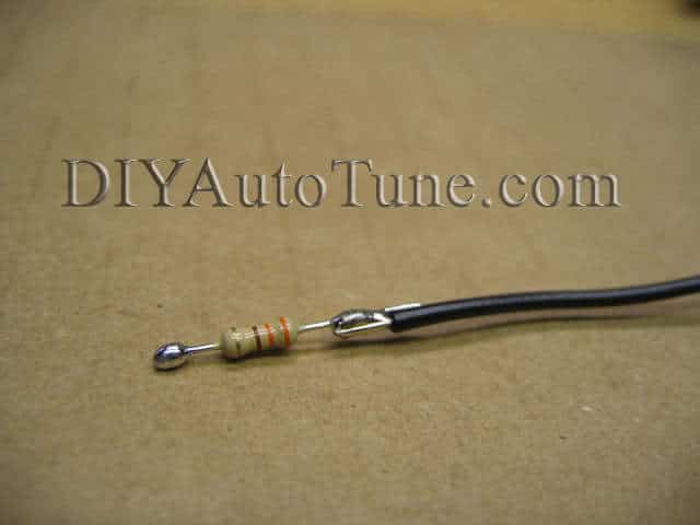
Get a 330 ohm 1/4w resistor and cut the leads down to about 1/2″ at each end. Maybe a bit less.
Tin each end of the resistor with a bit of solder.
Cut a 5″ piece of hookup wire (22ga is fine) and strip just a 1/8″ or so. Tin the stripped wire with solder.
Melt the tinned wire tip to one end of the tinned 330 ohm resistor tip and let it cool.
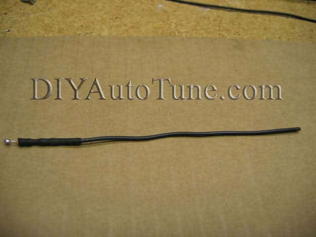
Heatshrink wrap this wire/resistor assembly.
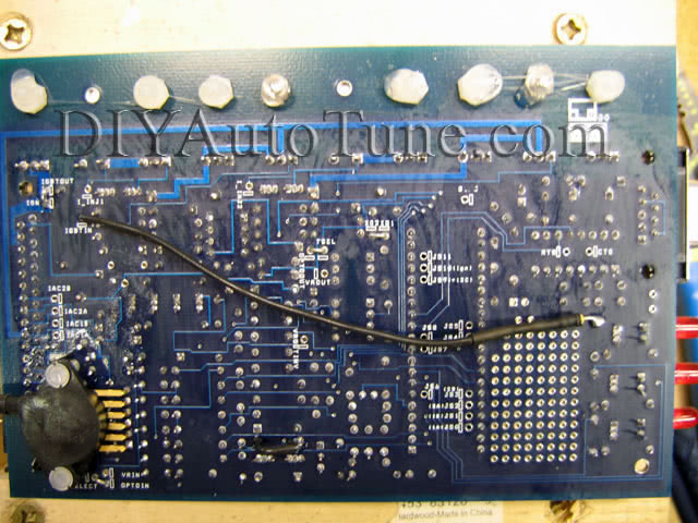
Use this wire/resistor combo to jumper the ‘top’ (top as in when you facing the silkscreen side of the PCB, with the text so that you can read it normally) lead of R26 to IGBTIN on the opposite side of the PCB.
External wiring:
Connect the VR sensor to pin 24 and the shielded ground wire.
Connect the negative terminal of the coil to pin 36.
Settings required:
Under Codebase and Output Functions:
Set Generic Wheel on, and all other code types off.
Set LED17(D14) Function to Spark Output A.
Turn off all other spark outputs.
Under Wheel Decoder Settings:
Some settings are the same for all engines.
Wheel decoder base teeth: 36
2nd trigger enable: Off
Missing Teeth: -1
Dual dizzy mode: Normal
Wheel decoder routine: 025 style
These settings are specific to your engine.
Number of Cylinders
Trig pos A
Trig return pos A
Trig pos B
Trig return pos B
Trig pos C
Trig return pos C
Trig pos D
Trig return pos D
Trig pos E
Trig return pos E
Trig pos F
Trig return pos F
4
3
8
21
26
0
0
0
0
0
0
0
0
6
35
5
11
17
23
29
0
0
0
0
0
0
8
35
4
8
13
17
22
26
31
0
0
0
0
12
2
7
8
13
14
19
20
25
26
31
32
1
Under Spark Settings:
Trigger Angle: 60 (Exception: 6 cylinder engines must use a trigger angle of 70.)
Trigger Angle Ignition: 0
Cranking Timing: Trigger Return.
Set Spark Output Inverted: Yes. Setting this wrong will overheat the BIP373.
Enable dwell control and adjust as needed to match the coil you are using.
Direct Coil Control Distributorless Ignition on a Megasquirt-I V3.0 or V3.57 Board
Using MSnS-E firmware
Hardware mods required:
Build the VR conditioner circuit. All our preassembled Megasquirts with the V3.0 or V3.57 board come with this circuit installed.
Jumper TachSelect to VRIN. (V3.57: Set JP1 to the 1-2 position.)
Jumper TSEL to VROUTINV. (V3.57: Set J1 to the 5-6 position.) Note: Depending on how your VR sensor is wired up, this can also be jumpered to VROUT or the 3-4 position. If you are unable to get a signal, you can either switch the jumper or the sensor polarity.
You may need to adjust the VR trim pots, R52 and R56, when this is installed on a running engine. A usual base setting is to turn them all the way counterclockwise.
Jumper IGBTOUT to IGN to send to IGBT ignition coil driver signal out of pin 36 on the DB37. (V3.0 only)
Cut out R57 if fitted (This won’t be there on my units, though.).
Now for constructing the outputs…
Get a 330 ohm 1/4w resistor and cut the leads down to about 1/2″ at each end. Maybe a bit less.
Tin each end of the resistor with a bit of solder.
Cut a 5″ piece of hookup wire (22ga is fine) and strip just a 1/8″ or so. Tin the stripped wire with solder.
Melt the tinned wire tip to one end of the tinned 330 ohm resistor tip and let it cool.
Heatshrink wrap this wire/resistor assembly.
Use this wire/resistor combo to jumper the ‘top’ (top as in when you facing the silkscreen side of the PCB, with the text so that you can read it normally) lead of R26 to IGBTIN on the opposite side of the PCB. (On a V3.57, this is kind of tricky. It’s easier to use pin 7 on the U1 socket instead.)
Now, you will be constructing duplicates of this BIP373 circuit for each coil output you need. For a 1 cylinder, you’ll use 1 output; for more cylinders, you will use 1 output for every 2 cylinders. You can mount the additional BIP373s on a second heat sink stacked on top of the first, attached on top with long screws. Or you can mount the BIP373s to the case.
Each BIP373 will need a resistor-on-a-wire assembly, running to its left leg. You will get the BIP373 input signal from the following locations:
Output
Input Location (V3.0)
Input Location (V3.57)
Spark A
Top of R26
U1 pin 7
Spark B
Top of R29
U1 pin 8
Spark C
Top of R27
U1 pin 9
Spark D
Bottom of R1 with R1 removed
Bottom of R1 with R1 removed
Spark E
JS7
JS7
Spark F
JS10
JS10
The center leg of the BIP373 is its spark output. We have found that the IAC traces can carry enough current for normal use, so you can use one IAC trace for each spark output. You may need to add an extra connector on 12 cylinder applications if you are not using a V3.57. This is our recommended pinout, which we use in our assembled ECUs, for up to 8 cylinder engines.
Output
Board connection
DB37 pin
Spark A
IGN
36
Spark B
IAC2B
31
Spark C
IAC2A
29
Spark D
IAC1B
27
Connect the right leg of each BIP373 to a ground, such as the proto area ground or SG pins. It’s best if you can find a separate ground for each BIP373.
External wiring:
Connect the VR sensor to pin 24 and the shielded ground wire.
Connect the negative terminals of the coil to the pins specified in the above pinout.
Settings required:
Under Codebase and Output Functions:
Set Generic Wheel on, and all other code types off.
Set one spark output for every two cylinders.
Turn off all unused spark outputs.
Under Wheel Decoder Settings:
Some settings are the same for all engines.
Wheel decoder base teeth: 36
2nd trigger enable: Off
Missing Teeth: -1
Dual dizzy mode: Normal
Wheel decoder routine: 025 style
These settings are specific to your engine.
Number of Cylinders
Trig pos A
Trig return pos A
Trig pos B
Trig return pos B
Trig pos C
Trig return pos C
Trig pos D
Trig return pos D
Trig pos E
Trig return pos E
Trig pos F
Trig return pos F
1 or 2
3
8
0
0
0
0
0
0
0
0
0
0
4
3
8
21
26
0
0
0
0
0
0
0
0
6
35
5
11
17
23
29
0
0
0
0
0
0
8
35
4
8
13
17
22
26
31
0
0
0
0
12
2
7
8
13
14
19
20
25
26
31
32
1
Under Spark Settings:
Trigger Angle: 60 (Exception: 6 cylinder engines must use a trigger angle of 70.)
Trigger Angle Ignition: 0
Cranking Timing: Trigger Return.
Set Spark Output Inverted: Yes. Setting this wrong will overheat the BIP373.
Enable dwell control and adjust as needed to match the coils you are using. Set the dwell at a very low value to start with (we’ve found Ford EDIS coils have especially short dwell times) and increase it slowly. Back it off if the BIP373s become hot to the touch.
EDIS on a Megasquirt-II V3.0 Board
Using standard MS-II Firmware
Hardware mods required:
If you’re assembling your MegaSquirt-II from a kit (Part# MS230-K):
Build the ECU up to trigger from the Hall/Optical Input.
Jumper JS10 to IGN to bring the ignition output directly to pin 36.
If you’re modifying a DIYAutoTune.com MS230-C MegaSquirt-II Assembled ECU:
No mods are required; our units are set up for EDIS out of the box.
External wiring:
Connect the EDIS PIP signal to pin 24.
Connect the EDIS SAW signal to pin 36.
Settings required:
Under “Base Ignition Settings,” make the following settings.
Trigger Offset: 0 degrees
Predictor Algorithm: Last Interval
Ignition Input Capture: Rising Edge
Cranking Trigger: Calculated
Coil Charging Scheme: EDIS
Spark Output: Going High (Inverted)
Distributor Based Ignition on a Megasquirt-II V3.0 Board
Using standard MS-II Firmware V2.687 or higher
Hardware mods required:
If you’re assembling your MegaSquirt-II from a kit (Part# MS230-K):
For the most part, stick with the standard assembly documentation in the MSExtra.com Hardware Manual. I’ll just be covering any departures from that doc here.
Step 51: You’ll be installing the VR input circuit (currently all steps under 51). You do not need the components in step 50, although it’s handy to install them in case you ever use the Megasquirt on a different car (or decide to convert your Mopar to a ignition system that uses this circuit).
Step 52: Set the jumpers for VR input. That would be TachSelect to VRIN, and TSEL to VROUT.
Step 65: You will use IGBT High Current Ignition Driver Circuit. That means you complete step 65. Install everything just as this step directs you to(which does mean no R57) and install the jumpers to enable the circuit. (IGBTIN to JS10 and IGBTOUT to IGN).
That’s it!
If you’re modifying a DIYAutoTune.com MS230-C MegaSquirt-II Assembled ECU:
Input Mod:
You will be using the VR input circuit. Connect the TachSelect jumper to VRIN, and TSEL to VROUT.
Output Mod:
There will be a jumper wire from JS10 over to IGN. Desolder and remove this (don’t just cut it, you’ll need the holes clear of solder).
Install new jumper wires to enable the IGBT High Current Ignition Driver Circuit (IGBTIN to JS10 and IGBTOUT to IGN)
External wiring:
Connect the VR sensor to pin 24 and the shielded ground wire.
Connect the negative terminal of the coil to pin 36.
Settings required:
Note that on a 1 cylinder, you must set the number of cylinders to 2 because there are still two ignition events per engine cycle.
You will configure the input under the “Advanced Ignition Options” page in MegaTune. Use these settings:
Number of Cylinders
Trigger Wheel Teeth
Missing Teeth
Skip Teeth
Delay Teeth
1
36
1
36
9
2
36
1
36
9
4
36
1
18
9
6
36
1
12
6
8
36
1
9
5
12
36
1
6
1
Under “Base Ignition Settings,” you will need to set Coil Charging Scheme to “Standard Coil Charge” and Spark Output to “Going High (Inverted)” to configure it for direct coil control. You will also need to adjust the dwell settings to match your coil.
Direct Coil Control Distributorless Ignition on a Megasquirt-II V3.0 or V3.57 Board
Using MS2/Extra firmware, version 2.0.0 or higher
Hardware mods required:
Build the VR conditioner circuit. All our preassembled Megasquirts with the V3.0 or V3.57 board come with this circuit installed.
Jumper TachSelect to VRIN. (V3.57: Set JP1 to the 1-2 position.)
Jumper TSEL to VROUT. (V3.57: Set J1 to the 3-4 position.)
You may need to adjust the VR trim pots, R52 and R56, when this is installed on a running engine. A usual base setting is to turn them all the way counterclockwise.
Jumper IGBTOUT to IGN to send to IGBT ignition coil driver signal out of pin 36 on the DB37. (not needed on a V3.57)
Cut out R57 if fitted (This won’t be there on my units, though.).
Now for constructing the outputs…
Get a 330 ohm 1/4w resistor and cut the leads down to about 1/2″ at each end. Maybe a bit less.
Tin each end of the resistor with a bit of solder.
Cut a 5″ piece of hookup wire (22ga is fine) and strip just a 1/8″ or so. Tin the stripped wire with solder.
Melt the tinned wire tip to one end of the tinned 330 ohm resistor tip and let it cool.
Heatshrink wrap this wire/resistor assembly.
Use this wire/resistor combo to jumper the ‘top’ (top as in when you facing the silkscreen side of the PCB, with the text so that you can read it normally) lead of R26 to IGBTIN on the opposite side of the PCB. (On a V3.57, this is kind of tricky. It’s easier to use pin 7 on the U1 socket instead.)
Now, you will be constructing duplicates of this BIP373 circuit for each coil output you need. For a 1 cylinder, you’ll use 1 output; for more cylinders, you will use 1 output for every 2 cylinders. You can mount the additional BIP373s on a second heat sink stacked on top of the first, attached on top with long screws. Or you can mount the BIP373s to the case.
Each BIP373 will need a resistor-on-a-wire assembly, running to its left leg. You will get the BIP373 input signal from the following locations:
Output
Input Location (V3.0)
Input Location (V3.57)
Spark A
Top of R26
U1 pin 7
Spark B
Top of R29
U1 pin 8
Spark C
Top of R27
U1 pin 9
Spark D
JS10
JS11
Spark E
JS5
JS5
Spark F
JS4
JS4
The center leg of the BIP373 is its spark output. We have found that the IAC traces can carry enough current for normal use, so you can use one IAC trace for each spark output. You may need to add an extra connector with the V3.0 on 12 cylinder applications, or if you are running a stepper IAC. You can use this pinout if you are not running a stepper IAC, for up to 8 cylinders.
Output
Board connection
DB37 pin
Spark A
IGN
36
Spark B
IAC2B
31
Spark C
IAC2A
29
Spark D
IAC1B
27
Connect the right leg of each BIP373 to a ground, such as the proto area ground or SG pins. It’s best if you can find a separate ground for each BIP373.
External wiring:
Connect the VR sensor to pin 24 and the shielded ground wire.
Connect the negative terminals of the coil to the pins specified in the above pinout.
Settings required:
Under Tach Input / Ignition Settings:
Set Spark Mode to “Toothed Wheel.”
Set the trigger angle / offset to 0.
Set Ignition Input Capture to “Falling Edge.”
Set Spark Output to “Going High (Inverted).” Setting this wrong can overheat the BIP373s or damage the coils.
Set Number of Coils to “Wasted Spark.”
Set Spark A output pin to D14.
Under Trigger Wheel Settings:
Some settings are the same for all engines.
Trigger Wheel Arrangement: Single wheel with missing teeth
Trigger Wheel Teeth: 36
Missing Teeth: 1
Wheel Speed: Crank Wheel
The Tooth #1 Angle setting depends on your number of cylinders.
Number of Cylinders
Tooth #1 Angle
1 or 2
80
4
80
6
50
8
40
12
9
Enable dwell control and adjust as needed to match the coils you are using. Set the dwell at a very low value to start with (we’ve found Ford EDIS coils have especially short dwell times) and increase it slowly. Back it off if the BIP373s become hot to the touch.