| If you haven’t already, please read the ‘disclaimer’ at the top of the parent page here.
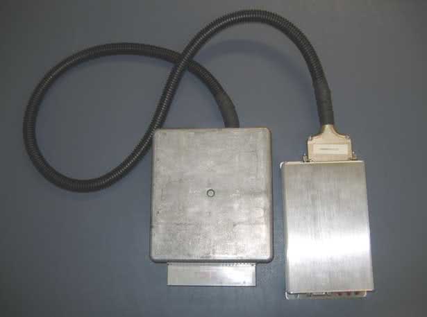
EEC-IV Adapter Board AssemblyScott Hall’s EEC-IV adapter board kit allows you to install MegaSquirt into virtually any Ford vehicle that uses an EEC-IV computer, without cutting a single wire. To get started, you’ll need both the kit and a donor EEC-IV ECU. You will first need to disassemble the donor ECU and desolder the main ECU connector from it. You can use a solder sucker or desoldering braid, or even (very carefully) burn off the solder with a propane torch. Alternately, you could build a short harness adapter using a MegaSquirt Wiring Harness and an EEC-IV ECU Connector.
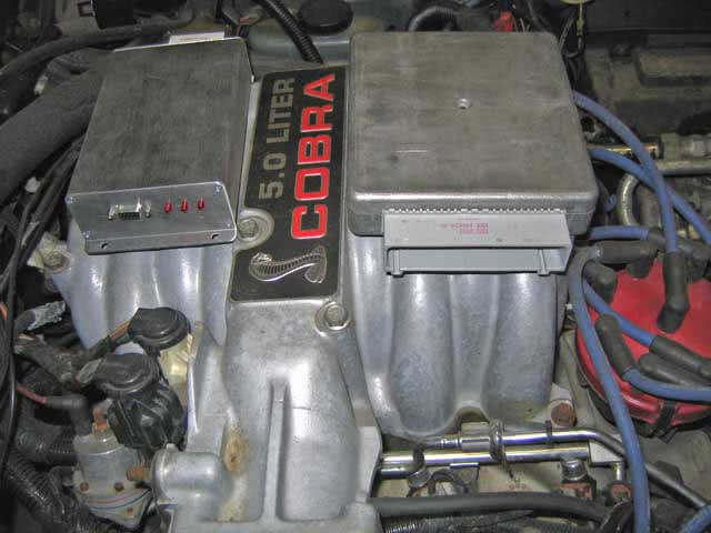
Relay controls, knock sensing, and moreThe EEC-IV adapter board has several controls for relays to drive fans and other output circuits. These closely resemble the MSnS-E relay driver circuits with the addition of a LED to let you know when the circuit is active. To use these drivers, run a jumper wire from the appropriate source on the Megasquirt board to one of the IAC outputs, and run a jumper wire from the appropriate pin on the EEC-IV adapter board to the AxIN hole in the relay output area. Then run a jumper from the AxOUT hole to the appropriate pin on the EEC-IV connector. These outputs can drive relays by providing a ground. The MSExtra manual section on relay outputs explains which area on the Megasquirt mainboard corresponds to which output number in MegaTune. With Megasquirt-II, you use its spare output port settings to operate the relay drivers. In either case, you will just need one length of jumper wire inside the Megasquirt itself; the EEC-IV adapter board has the rest of the circuit. For example, if you have a fan control circuit on pin 52 of the EEC-IV connector, and want to drive it from the JS2 port (that’s Output 1 on MS1/Extra, or a stepper IAC output on MS2) on the MegaSquirt, and use the A1 output on the EEC-IV board, you would wire JS2 to the IAC1A jumper on the MS, the IAC1A jumper on the adapter board to A1IN, and A1OUT to the pin 52 jumper. The switch circuits work in a similar fashion. They’re designed to take a voltage input and send it to Megasquirt for table switching or nitrous control. In this case, the “In” side will go to the EEC-IV connector, and the “out” side to Megasquirt. The EEC-IV adapter board also incorporates the knock sensor circuit from the MSExtra manual. You can wire its input to an external knock sensor and send its output through the relay cable to the appropriate pin on the Megasquirt. With MSnS-E, you will use pin 5 on the JP1 header for a V2.2 board, or the JS10 jumper on a V3.0 board. With Megasquirt-II, you need to use pin X6 for a V2.2 board or JP4 on a V3.0 board. You can also use any of the other MSnS-E circuits and send their output straight from the Megasquirt to the EEC-IV connector by running the appropriate jumper wires. Note that the standard relay cable has the IAC wires, but not the four SPR wires. The EEC-IV adapter board has a PWM IAC driver circuit. You can also have a PWM output circuit in the Megasquirt; in that case, leave out the PWM driver components and jumper PWM IN to PWM OUT. V2.0 boards need you to run the thin jumper wire (included with the board) from the spot where R25 and R26 connect to a 12 volt hole in the proto area in order to make the PWM circuit functional. V2.1 boards do not need this jumper. To check if the board version you have needs this junper, measure the resistance from the connection between R25 and R26 to the 12 volt hole in the proto area. If it’s near zero, no jumper is needed. Setting up the jumpersTo configure the jumpers, you will need a wiring diagram for the car you are installing your EEC-IV adapter onto. While the ignition, power, and temperature sensor lines are the same, you will want to check the pins for the injectors, oxygen sensor, and any relay outputs you may need to use. Here are the jumper settings for one of the most popular EEC-IV cars ever, the ’86-’93 Mustang with the 5.0. This setup appears on MegaScott’s documentation; we have not tested it yet on an actual running 5.0 ourselves. This arrangement fires the #1, 6, 7, and 4 injectors on one bank, and the #2, 3, 5, and 8 on a separate bank. It only uses one oxygen sensor; you can add extra hardware to the Megasquirt for a second oxygen sensor output and change the injector connections to have each bank controlled separately, too.
We’ve also found that if you are preparing for a swap and want to check out your EEC-IV adapter board before you drop a 5.0 into a four banger car, you can make the 5.0 jumpers work on a ’88 2.3 Mustang (and quite probably other years) by disconnecting the EGR valve. As you may have guessed, we’re planning to put a 5.0 into our Mustang test car and test these settings out very soon – stay tuned!
The EEC-IV adapter board is also popular with the 2.3 Turbo crowd. On these cars, the ECU often controls the boost. Since there is no boost control provision in the EEC-IV adapter board, you’ll need to install our MK-Boost mod kit for boost control in the Megasquirt (see here for MS1/Extra & MS2/Extra) and bring its output to the IAC1A pin on a V3.0 / V3.57 board or X11 on a V2.2 (do not install the stepper IAC jumpers) if you want to retain this feature. Set up the board following the TFI directions above. Optionally, you may want to use the knock sensor input circuit on pin 31 (IAC2B or X14). The jumper setup below works for the following applications: 1983-1984 Ford Thunderbird Turbo Coupe and Mustang SVO 1989 Mercury Merkur XR4Ti (no electronic boost control)
1985-1986 Ford Thunderbird Turbo Coupe and Mustang SVO 1985-1988 Mercury Merkur XR4Ti
For the 1987 and later Turbo Coupe, the ECU controlled the fans. You’ll also need two generic relay control outputs on pins 27 (IAC1B or X12) and 29 (IAC2A or X13) for fan outputs on this model. 1987-1988 Ford Thunderbird Turbo Coupe
|