Now that we’ve assembled the main board and adapter board, we’ll install the basic jumpers to provide the DIYPNP with power, grounding, sensor inputs, and injector outputs. These jumpers simply run from a pin on the lower edge of the DIYPNP main board to the appropriate holes in the adapter board. First, we recommend you check our available DIYPNP Models page to see if we have a how to guide for your specific car. If we do not, you’ll want to consult a pinout of your stock ECU. You’ll also want to get a copy of the setup spreadsheet from our DIYPNP downloads page, as this can help organize the process.
Once you’ve got an ECU pinout, the first step is to figure out how the pin numbering on the DIYPNP matches the pin numbering on your own ECU. On some models, it’s quite simple; the Bosch 55 pin board, for example, always simply numbers its pins 1 through 55, and the numbering scheme does not change from car to car. On the Nippondenso-derived connectors, each manufacturer had their own numbering system, which sometimes changed depending on how many of the connections are used. So you will need to match the factory wiring pin numbering system up to the DIYPNP pin numbering system first. Here is how the pins on the DIYPNP connectors are numbered. Click on the pictures for a closer, clearer view.
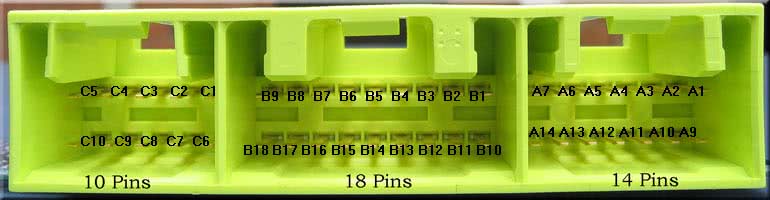
N42 pins:
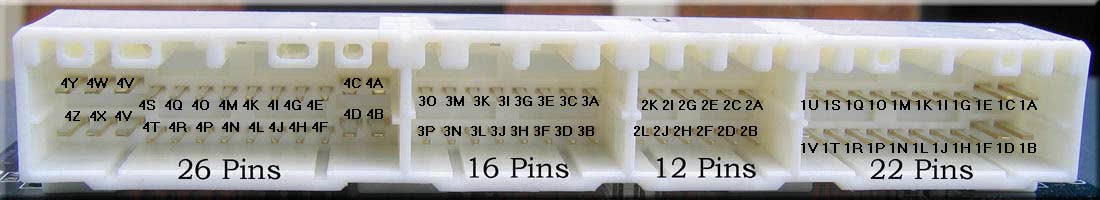
N76 pins:
Once you’ve identified which pins you’ll need for the stock ECU, you’ll need to match them up to the output pins on the DIYPNP. We’ll start by matching up the basic connections for power, sensors, and injectors. We’ll cover RPM input, ignition control, and some of the advanced input and output functions once this is complete. Here are the pins we’re going to focus on for now, and what the pins do. You’ll be able to find them all along the lower edge of the mainboard.
- IAT – Intake air temperature sensor input
- CLT – Coolant temperature sensor input
- TPS SIG – Throttle position sensor signal
- O2 SENSOR – Oxygen sensor input
- FUEL PUMP – Signal to drive a fuel pump relay.
- INJ 1 and INJ 2 – Each of these headers has four connections and can drive four high impedance injectors. All four holes for each injector function the same.
- 12V – Use these connections to supply 12 volt power to the board.
- VREF – 5 volt reference voltage for sensors. Do not tie VREF to the main board 5V points.
- 5V – 5 volt power voltage from the main board voltage regulator. This is meant for powering 5V devices in the proto area. Do not connect this to VREF or analog sensors.
- SG – Signal ground, for sensor returns.
- GND – Power ground.
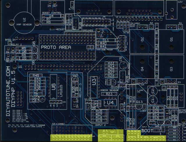
The locations of the jumpers on the main board that you’ll be using in this step are marked in yellow on the picture below. The X-Connect section is for future hardware.
Power and Ground
As you’ve noticed, there are five separate types of power and ground connections on the DIYPNP. Each of them has its own specific purpose. Here is what each connection does.
12V: This connection powers the DIYPNP. Connect it to the pin(s) which get 12 volt power when the ignition key is in the Run and Start positions. We’ve provided you with several 12V pins in case your ECU has more than one. These should not be connected to any pin that receives 12 volt power when the key is off, but only to 12 volt switched power connections.
VREF: This connection provides a 5 volt reference voltage for the throttle position sensor, and can be used for some other types of sensors, such as external MAP sensors. These connections are usually marked with something like “5V,” “VREF,” or “Reference Voltage” in the factory wiring diagram. Caution: Do not let the VREF connection be shorted to ground – this will shut down the DIYPNP. Also, do not tie VREF to the main board 5V power supply (points marked 5V).
5V: The DIYPNP has a second power supply for 5 volt circuits that are isolated from the main reference voltage. Usually you won’t need to connect this to any external wires (it’s more useful for onboard circuits), though if you run across a Hall effect or optical sensor in the external wiring that needs to be supplied 5 volt power, use this jumper. Do not connect to VREF.
SG: Sensor ground. If you have common ground wires coming back from external sensors, connect the pins these wires use to the SG jumper. This is to reduce the amount of noise in signal wires.
GND: Power ground. Connect any ground wires that go to the engine block, battery terminal, or chassis ground to the GND jumpers.
Sensors
The throttle position sensor, temperature sensors, and O2 sensors are fairly straightforward to hook up. The VREF and sensor grounds are covered above; now here’s what to do with the sensor input pins themselves.
IAT: The intake air temperature sensor may be a freestanding sensor, or it may be built into an air flow meter. It generally has two wires, the signal wire and the sensor ground wire. The signal wire goes to IAT and the ground wire goes to SG. Usually the ground wire will merge into another ground wire in the external wiring; in the rare event that you find an IAT sensor where neither wire connects to others or has a clear function, it can be wired up either way.
CLT: The coolant temperature sensor wires up exactly the same way as the IAT sensor.
O2 SENSOR: Narrow band O2 sensors come in one, three, and four wire flavors. With a one wire sensor, simply connect that one wire to the O2 SENSOR jumper. Sensors with more wires will also need the signal ground connected to SG, but they’ll generally work OK without the heater circuit connected. It just takes them longer to warm up. The DIYPNP does not read wideband sensors directly, requiring an external controller. If using one of these, wire the controller’s analog output to the O2 SENSOR jumper.
TPS: The TPS’s signal wire goes here. It is usually marked in the diagram about which is the signal wire. If it isn’t, you’ll need to test the TPS with an ohmmeter. Observe the resistance as the throttle opens and closes. Each pair of pins will behave differently:
The resistance between the VREF and ground pins will remain constant.
The resistance between the ground and signal pins will be low with the throttle closed and high with the throttle wide open.
The resistance between the VREF and signal pins will be high with the throttle closed and low with the throttle wide open.
If your sensor behaves like this, it will be pretty straightforward to connect it to Megasquirt.
If the resistance jumps from infinite (or near infinite) to near zero, you have a switch type throttle position sensor, or possibly a seriously defective potentiometer type TPS. These do not provide very much information that Megasquirt needs, as it can tell if you are at idle or full throttle by the MAP sensor information. You can still use MAP based acceleration enrichment and ground the TPS signal pin through a resistor.
Fuel Control
INJ1 and INJ2: These are your injector outputs. The DIYPNP is batch fire normally, so you will be using two outputs, each of which can drive one low impedance or four high impedance injectors, so each of the four INJ1 holes are the same, and each of the four INJ2 holes are the same. The INJ1 and INJ2 jumpers connect to the injector wires on the adapter board. Usually the best way to pair them is by firing order – connect the first cylinder to fire to INJ1, the second to INJ2, the third to INJ1 again, and so forth. This isn’t a hard and fast rule, and some harnesses will make the injector pairing choice for you. Usually it’ll run fine with pretty much any injector pairing anyway, though some pairings may be a little bit smoother.
Note that there are holes marked 3 and 4 above the INJ2 header. These are wired to the holes marked 3 and 4 in the proto area. These let you jumper a sequential add-on board to the holes in the proto area, making for fewer awkward long runs of wiring.
FUEL PUMP: This pin supplies a ground for the fuel pump relay. Most ECUs will have a ground pin for the fuel pump relay wired straight to the ECU, so you just have to find this wire on the adapter board and connect it to the FUEL PUMP pin on the main board. Some cars, however, have the fuel pump controlled by a switch in the air flow meter. If this is the case, you have two choices on most cars:
- Leave the air flow meter in place and don’t connect the FUEL PUMP jumper to anything. The fuel pump will still operate more or less normally.
- Remove the air flow meter and connect the FUEL PUMP jumper to a wire previously used by the air flow meter. At the air flow meter connector, splice the wire that is now going to the FUEL PUMP jumper to the wire that goes to the fuel pump relay.
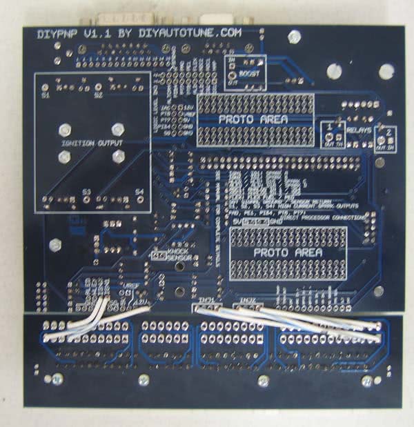
This picture shows a V1.1 DIYPNP partially jumpered (V1.5s jumper up the same way). Note that these jumpers are being put in on the underside of the board – the main board is marked on both sides, although not all adapter boards are.