Ignition control is one of the more involved parts of the DIYPNP installation to set up, and may take a bit of trial and error if you do not have an application guide to cover what mods you need. This page will explain the ignition control, both the inputs and the outputs. We’ve made the DIYPNP flexible enough to cover many different types of possible ignition systems.
- Inputs
- Outputs
Ignition Inputs
The MicroSquirt Module has three ignition input circuits, two which can be used for various types of crankshaft position sensors and a third for camshaft position sensors (aka second trigger or G sensors). Here’s how to tell which circuit you need.
Some ECUs only control the fuel and get their RPM signal off the negative terminal of the coil. If you have one of these, connect the ECU pin that goes to the coil negative to OPTO IN + and connect OPTO IN – to a 12 volt pin through a 4.7K resistor. A version of this uses a 12 volt square wave instead of the coil negative; if you have this, connect OPTO IN + to the signal connection and put a jumper across the two pins of Opto GND.
For an optical or Hall effect crankshaft position sensor, most of the time you’ll wire OPTO IN + to the sensor and put a jumper across the two pins of OPTO GND. Many of these need a pull up resistor; in most cases, a 1K resistor in the 12 volt position on R3 will do the trick. There are a couple of other circuits you can try if this doesn’t give a steady signal. The most common versions are to use different pull up resistors, or to remove the Opto GND jumper, do not connect OPTO IN +, and connect OPTO IN – to the sensor. If connecting Opto IN – to the sensor, you must have a pull up resistor – the circuit won’t work without it. This version requires the opposite Ignition Input Capture setting from the normal version.
Variable reluctor sensors, sometimes called VR sensors, inductive pickups, or magnetic pickups, have two wires, and possibly a third shield wire. Connect the positive wire to VR+ and the negative wire to VR-. Sometimes it may take a bit of trial and error to find out which is which since factory wiring diagrams often do not mark these clearly. If you have a shield wire, connect it to GND. Tip: If your sensor is connected to a wheel with a large number of teeth, like a Ford 36-1 or a Bosch 60-2, and you’re losing the tach signal at high RPM, put a 10K resistor in line with the wire going to VR+. This will usually clear things right up.
The camshaft position sensor input is marked VR2. It’s actually a kind of hybrid circuit that works with Hall effect, VR, and optical sensors. Hall or optical sensors may need a pull up, just like with the crankshaft position input. VR sensors with a separate ground wire should have this wire connected to SG. The VR2 circuit has a built in threshold that some VR sensors may not trigger correctly at low RPM. If this happens on your car, take a 51K resistor and install it in the R21 position. This will lower the threshold voltage. Many Nippondenso ignitions will need this mod. For other sensors, you can install R39 to make the trigger voltage user-adjustable, or use R20 to pull up the trigger voltage to reduce noise.
The V1.5 DIYPNP adds an extra VR conditioner called an LM1815. You can use this circuit if you experience difficulty using the regular VR conditioner circuit. Usually you will not want to use the “timer off” jumper. This one connects with a four position header below U6, which we’ll call the LM1815 header. The VR+ and VR- terminals are for input to the LM1815, not the main VR conditioner. The hole marked “OUT” is the LM1815 circuit output, and the hole marked “TO VR2” lets you patch this circuit over to the cam input.
To use the LM1815 for the camshaft position sensor, wire the camshaft position sensor to the VR+ and VR- on the LM1815 header, then connect OUT to TO VR2.
Using the LM1815 with the crankshaft position sensor is a bit more involved. Here are the steps to set this up.
- Connect the crankshaft position sensor to VR+ and VR- on the LM1815 header.
- Connect the OUT terminal on the LM1815 header to Relay 3 In.
- Install a 470 ohm pull up in the R3 position to 5 volts.
- Connect Relay 3 Out to OP- on the edge of the DIYPNP main board.
Ignition outputs
Depending on your ignition module, there are several possible circuits you can use. Here’s a guide to the various options.
Basic Logic Level Output
Rule of thumb: This is the most common spark output configuration on Mazda, Mitsubishi, and Toyota vehicles. If you have one of these cars, try starting with this setup.
On cars that use this, the ignition module is controlled by a voltage signal from the ECU. Usually, it starts charging the coil when it gets a 5 volt signal from the ECU, and fires the coil when the signal goes back to 0 volts. This is a fairly simple setup. Just start with the four pin header near Input 1, and jumper these outputs to your ignition module connections on the adapter board.
Spark A: IGN1
Spark B: IGN2
Spark C: WLED (requires MS2/Extra 2.1.1 or higher)
Spark D: ALED (requires MS2/Extra 2.1.1 or higher)
Spark outputs C and D also need pull ups. A typical pull up setup is to put a 100 ohm resistor in the 5 volt position for both R1 (spark D) and R2 (spark C).
Virtually all setups that use this mod will have the spark output set to Going High / Inverted. Check to be sure the ignition module doesn’t get hot when you have the key on and the engine off; if it does, reverse the spark output setting.
Direct Coil Control
Rule of thumb: If your coil has only two terminals, and there’s no ignition module outside the ECU, use this. Also applies to 4 cylinder coil packs with 3 terminals and 6 cylinder coil packs with 4 terminals when not used with an external ignition module.
Common in Bosch and Seimens ECUs, almost unheard of in ECUs of Japanese origin. There is no external ignition module, and the ECU controls the current running through the coil directly with a power transistor. You can order BIP373 power transistors to install in the DIYPNP for these types of ignitions. On cars which originally used an external ignition module, this can open up other ignition options directly controlled by the ECU. For example, if you want to convert your ’90-’97 Miata to use one MSD coil for each plug, you can use these outputs to fire the coils without an external ignitor.
The BIP373s install in the Q1 through Q4 slots, using a heat sink as included in the DIYPNP BIP373 mod kit. Here’s what components are in each spark circuit.
Spark A: Q1, R13
Spark B: Q2, R12
Spark C: Q3, R11
Spark D: Q4, R10
When using the high current ignition drivers, they must be enabled with the jumpers marked High Current Driver Select. These jumpers are marked S1 through S4, for spark outputs 1 through 4 respectively. To enable the first two high current drivers, jumper the lower holes to IG1 and IG2. The second two may be enabled in sequential or wasted spark fashion. Jumpering the middle holes to WLD and ALD will trigger these from WLD and ALD respectively, allowing for sequential coil on plug on a four cylinder or wasted spark on a six or eight. Jumpering the center holes to IG1 and IG2 will allow “wasted spark COP” output on a four cylinder, letting you use two processor outputs to fire four coils in a wasted spark fashion.
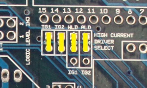
The picture above shows it jumpered for four separate spark outputs. You’d set it up this way for 4cyl sequential ignition, or for 8-cyl wasted spark (using two 4-tower wasted spark coil packs). All outupts, S1, S2, S3, and S4 would be used. These are the outputs to the ignition coils.
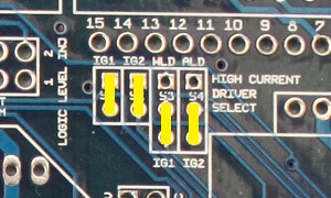
Changing the second two jumpers drives all four transistors from the IG1 and IG2 signals for wasted spark COP on a 4cyl. (Wasted spark COP means having an individual coil for each cylinder, but firing them in pairs in a wasted spark manner.) You would still use all four outputs with this configuration, S1, S2, S3, and S4.

Using only the first two jumpers as in the above image would control a 4cyl wasted spark configuration, such as controlling either one 4 tower coil pack, or two dual tower packs. This setup would use only outputs S1 and S2.
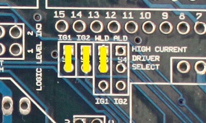
The above configuration would be for either 3cyl sequential or 6cyl wasted spark. Outputs S1, S2, and S3 would be used for this setup.
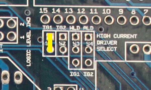
Using only the first jumper would be the correct configuration for direct control of a single coil used with a distributor. Only output S1 would be used in a single coil setup.
If using spark outputs C or D, you’ll need to install 100 ohm, 5 volt pull up resistors in the R2 and R1 slots respectively.
Spark A: S1
Spark B: S2
Spark C: S3 (requires MS2/Extra 2.1.1 or higher, or wasted spark COP jumpers)
Spark D: S4 (requires MS2/Extra 2.1.1 or higher, or wasted spark COP jumpers)
Spark output must be set to Going High / Inverted.
Ground Triggered Logic Level
Rule of thumb: If it’s a Honda and has a distributor, use this.
A much rarer sort of ignition module, but examples that do this include the Bosch 139, most Hondas, and the MSD 6AL also falls into this category if you have its white wire connected directly to the DIYPNP (If you have it connected to a stock ignition module, base your mods on what the stock ignition module would need). A ground triggered ignition module doesn’t run the coil current through the ECU, but instead it pulls a signal on the factory ignition module to ground. For Honda ignition modules, connect IGN1 to the In terminal on Relay 1, and connect the Out terminal of Relay 1 to the ignition module pin on the adapter board.
Spark output must be set to Going High / Inverted.
Note that this specifically applies to Honda’s distributor based ignitions. The D17 coil on plug uses basic logic level output.
GM HEI
Rule of thumb: If you have a GM with HEI 7 or HEI 8 module, use this.
The GM HEI 7 and 8 pin modules are simple to work with. It should be noted that electrically the 7 and 8 pin modules are pretty much the same, the difference being the 8 pin module has an extra pin, G, which is simply an extra ground. Here is the pinout:
| HEI Module Pin | Function | Connection |
| R | Tach Signal | DIYPNP Opto- |
| E | Advance Control | DIYPNP IGN1 |
| B | Override (cranking) Signal | DIYPNP IGN2 |
| P | VR Input + | VR Sensor + |
| N | VR Input – | VR Sensor – |
| + | +12V | +12V |
| C | High Current Coil Ground | Coil – |
| G (8 pin only) | Ground | Ground |
You will need to install a pullup for the tach input signal to the DIYPNP. A 470ohm resistor to 5V at the Opto+ (R3) position should do it. Make sure that you do not install the Opto Ground jumper.