Updated 12/8/2020
So, you’re putting the MS3 in a car with ECU controlled gauges – or that engine you’ve swapped in doesn’t have the right sensors to run your existing gauges. In many cases, the MS3 is able to take over control of the gauges.
Tachometer
The MS3 has a dedicated tach output channel – in many cases, simply connecting your tach trigger terminal to the MS3’s tach output is all you need when it comes to the wiring. You will need to turn the tach output on in TunerStudio.
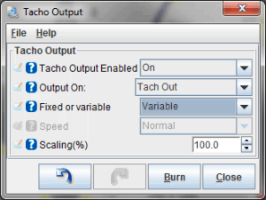
Current MS3 firmware has a variable tach output feature. This lets you set the tach output to anywhere from 10% to 10 times tach speed. Using a six cylinder tach on an eight cylinder engine? No problem – just set your tach scaling to 75%? Stock tach calibration a little off? Just adjust this number until everything matches.
Note that some tachometers that originally triggered off the coil may not work with the MS3 tach output’s 12 volt signal. For these applications, use our AMX-100 tach adapter module to step up the output voltage.
Speedometer
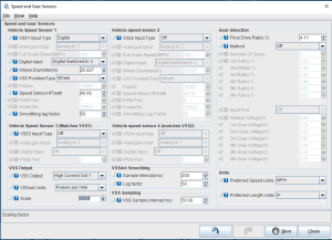
The MS3 also has a speedometer output. You’ll need to connect a VSS input, and the output may need a pull up if the gauge itself doesn’t have one. MS3 firmware allows you to set speedometer output in pulses per mile or pulses per kilometer.
Other analog gauges
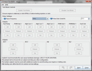
The MS3 does not have dedicated outputs for other gauges. However, you can spoof the output of a one-wire sending unit using a generic PWM output, as long as your gauge has enough damping. To wire this up, connect the gauge to a high current output (for an MS3Pro) or mid current output (for MS3X). Next step is to calibrate the output. To do this, go to Output Test Mode – I/O. The gauge output can vary depending on what frequency you use to drive it; we recommend using 78 Hz, the fastest frequency available in test mode. Set the output to “pulsed” and note what pulse duty cycle gives you what reading on the gauge.
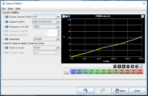
Next, we’ll set up a generic PWM output under the Advanced Engine menu. Select which output pin you’re using, and set the load axis to the measurement that controls the gauge. You’ll normally want to use a curve instead of a table. Here, you’ll enter the sensor reading you want for the load, and the duty cycle needed to obtain the desired reading. The curve below was used to run the coolant temperature gauge on a 1971 Chevy C10 pickup.
CAN Bus Driven Gauges
Some OEM gauges operate over CAN. The development team has added support for a few select gauges, accessible under the CAN Broadcasting menu. Support for other CAN dashes may be added in the future, while dashes that use other data hardware besides CAN may be supported by future expansion modules.
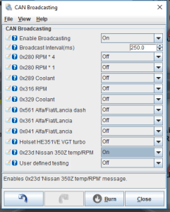
• 0x280 RPM * 4, 0x280 RPM * 1, 0x289 Coolant: Used in Porsche instrument clusters (the 996 is one known application) and some Volkswagens. You will need to test if you need the *4 or *1 multiplier on RPM output, depending on the vehicle.
• 0x316 RPM and 0x329 Coolant: Used on E46 chassis BMW instrument clusters. Note: Some users report this needs a 50 ms broadcast interval to work correctly.
• 0x561, 0x361, 0x041 Alfa / Fiat / Lancia: Used in some mid 2000s cars from these manufacturers.
• 0x23d Nissan 350Z temp / RPM: Used on Z33 chassis Nissan 350Z.
Aftermarket Race Dashes
Many third party race displays have built in support for the MS3’s CAN or serial protocol. See this link for known supported aftermarket dashes.