Bitwise Operations and Loops
This is an advanced level topic. Be sure you have read and understand Part 1, Basic On/Off Outputs before continuing with this article.
[section 7.8.23 in the MS3Pro manual]
Bitwise operations enhance programmable outputs by allowing the creation of custom functions. For example, you can use a single button for dual purposes based on specific conditions you setup.
Some examples:
- Enabling a High Boost Table Switch ONLY IF the oil temperature is above a set temperature
- Activating a transmission dump solenoid during 2-step ONLY IF with MAP is below a specified level
Bitwise Operations are particularly effective in triggering events tied to Status, CELStatus, or Port fields. When operating in this mode, the Threshold and Hysteresis values function uniquely. The output is activated when the result of a bitwise AND operation between the parameter and the threshold equals the hysteresis value.
Loops serve as virtual outputs, simulating input switches. They can activate features typically controlled by on/off inputs, such as table switching or launch control. Additionally, loops generate a bitfield that can be employed with the AND operation on other on/off outputs.
Input Sharing Example
What this allows us to do is setup I/O based on these “events” for example if we wanted to use the same button for both our Bump Box and Scramble. We have outlined this example below along with covering the basic settings for Launch and Transbrake as these are necessary in this example.
Launch and Transbrake Settings
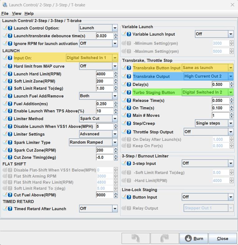
Highlighted in yellow One Button for two functions (Built in the software):
- Launch (Input Pin) – Digital Switched In 1 = Input On,
- Transbrake (Transbrake Button Input) – Transbrake Button Input = Same as launch
- This allows you to share the same input for both Launch and Transbrake with the same button
Highlighted in Green/Blue One Button for two functions (NOT Built in the software)
- Bump Input Pin (Turbo Staging Button) – Digital Switched In 2
- Bump Output Pin (Transbrake Output) – High Current Out 2
- Scramble – This feature is NOT built into the software, so will need to use Bitwise operations and Loop. Follow the example below on how to set this up.
Example on How to Setup a Bitwise Operation and Loop
We are now going to use the above example for Scramble. First step, we will need to set up Bitwise Operation as Input/Output pins function opposite of each other. We have outlined this below.
Bitwise Operation Functions:
- Input Pin
- Button NOT pressed = Active = Port Value
- Button pressed = Not Active = 0
- Output Pin
- Output is ON = Active = Port Value
- Output is OFF = Not Active = 0
Example Setup:
- Bump (Turbo Staging Button) – we selected Digital Switched In 2 under Transbrake, Throttle Stop
- Scramble – we need to use a Loop to use the same button as Bump
- First, we need to identify the Port for Digital Switched In 2 as shown in the ECU manual or TunerStudio Reference Guide.
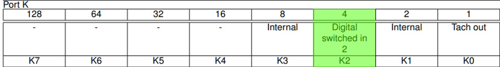
Each Port has 8 bits giving us 6 options per Port, these bits are binary. Bit K0 has a binary value of 1, as the Bit value increases the binary value doubles. This makes it so no combination of bits will add up to equal a higher bit value.
- Digital Switched In 2 has a value of 4 on Port K.
- We want Digital Switched Input 2 to have two functions:
- Function 1 – trigger a bump event when the transbrake is Active
- Function 2 – trigger a scramble event when the transbrake is Not Active.
To ensure each function is triggered at the right time, we want to look at when the Transbrake is Active. In our example, Transbrake is controlled by Output High Current Out 2, so we want to:
- DISABLE Scramble when High Current Out 2 is Active, since we Do Not want Scramble Active until needed, so we want to stop the loop if Transbrake Output High Current Out 2 is Active.
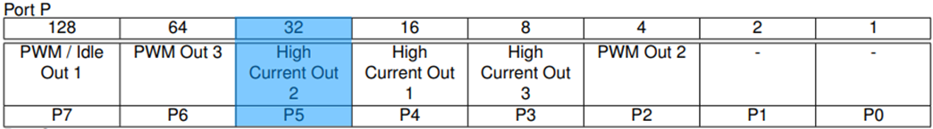
- High Current Out 2 has a value of 32 on Port P when it is NOT Active
Loop Settings
Now that we know the Bitwise Operation, we can setup the necessary Loop for Function 1 (Bump) and Function 2 (Scramble). Below is a breakdown of the steps for this example:
Step 1 – Navigate in TunerStudio to:
Step 2 – Select the Loop you will be using. In this example we are using the below Output Port:
- Loop 1
- Select Loop 1 as our Output Port in the menu on the left, then click on “Enabled” under Port Settings
- Once Enabled is checked, the Port Settings and Active Conditions options below will become editable (ungrayed out) allowing you to setup the output as desired
Step 3 – Under what conditions do we want the Loop to come Active?
- Active Conditions – this section is where we set the conditions for the output change to become Active
- Output Channel – this is a variable from the ECU to be used to trigger the channel
- In this case, our output channels are going to be Port P and Port K from the bitfield tables above
- Operator
- AND (logical AND statement)
- AND/OR – this allows you to add an additional condition if desired
- AND – this option makes the output channel active IF BOTH CONDITIONS are met
- OR – this option makes the output channel active IF EITHER CONDITION is met
- Threshold – the Output Channel is compared with the Operator against this value. If the condition is “true” then the output will become active
- Hysteresis – this is how much the value must move before the condition is “false”, consider this a deadband +/- this value where the condition will remain active
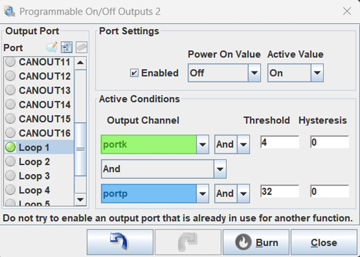
- We will set our Power On Value to Off
- We do not want to either function Transbrake or Scramble to be Active when turning the ECU ON
- We will set our Active Value to On
- We will want either Transbrake or Scramble to be Active ONLY WHEN, we press the Digital Switched In 2 button (as long as other required conditions are also met)
Now we will work on our Active Conditions, but first here is some background information on how an ECU “thinks”. This is important because we have to know what the ECU is thinking in order to properly set up our Bitwise Operations.
- External Bump/Scramble button wired One side to Ground and other side to Digital Switched Input 2
- When the button is Not Pressed
- Digital Switched Input 2 is “High” making Port K = 4 bits and Active
- When the button is Pressed
- Digital Switched Input 2 is “Low” making Port K = 0 bits and NOT Active
- Transbrake button wired to High Current Out 2 and outputs works OPPOSITE as the above input
- When the Transbrake is Not Commanded Active,
- the processor pin is “Low” and Port P = 0.
- When the transbrake is Commanded Active,
- the processor pin goes “High” and Port P = 32
- The “High” processor pin then triggers a MOSFET (a transistor inside the ECU) to ground the transbrake solenoid.
- When the Transbrake is Not Commanded Active,
- When the button is Not Pressed
So, Input and Outputs have Bitwise Operations logic that appears to be backwards from each other! We want our Loop to only be active when the Digital Switched Input is ON and the Transbrake is OFF… but because the inputs and outputs are inverted from each other, our programming will look the same.
- Port k is Active (Port K = 4) when the input Digital Switched In 2 is Not Active. When The Digital Switched In 2 is ACTIVE (Button Pressed) the ECU is pulled down to ground, Pork K becomes inactive and Port K = 0.
- We set our Port k “threshold” to 4 and “hysteresis” to 0. This tells the ECU to watch the status of the Digital Switched In 2
- When the ECU sees Port k switch from 4 bits to 0 bits (Bump button PRESSED), the first Active Condition is true.
- Port p is Active when the transbrake is triggered on High Current Output 2. The transbrake relay is pulled to Ground and Port P = 32.
- We set our Port p “threshold” to 32 and “hysteresis” to 0. This tells the ECU to watch the status of High Current Output 2. When the Transbrake is Active and Port P = 32, we DO NOT want Scramble to function. However, we do still want our Bump button to function.
- When the ECU sees Port p switch from 0 bits to 32 bits (meaning the Transbrake is Active), the second condition is false. When the transbrake is not active, the second condition is true.
- Both active conditions must be true for the Loop to be active.
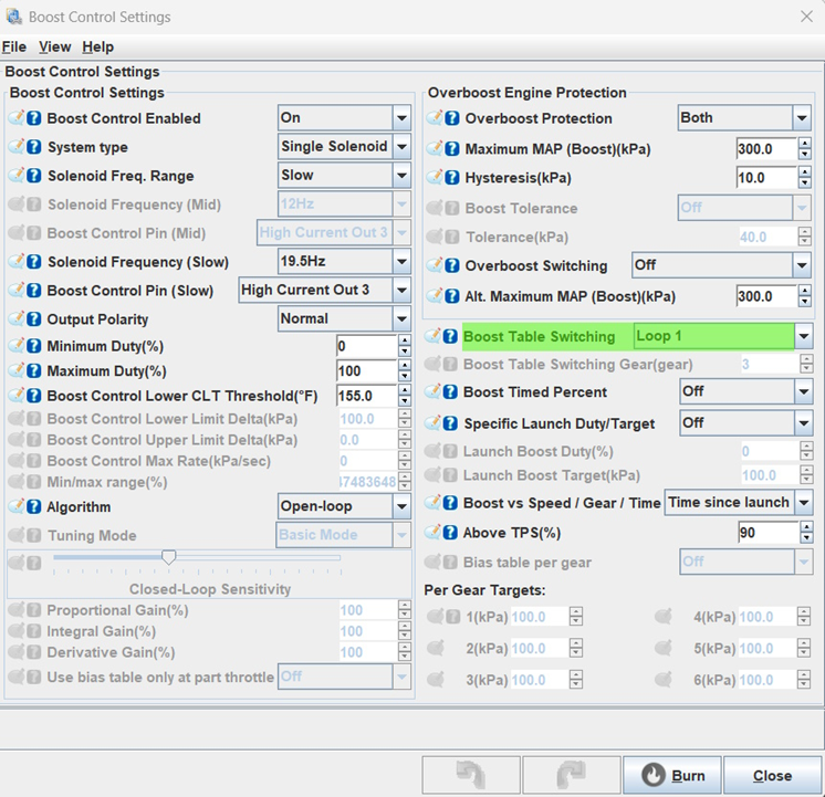
Scramble button on Loop
Now that Loop 1 is setup to be active when the external button Digital Switched In 2 is grounded, but not when our transbrake solenoid on High Current Out 2 is being commanded, we can assign boost table switching to use Loop 1 as its trigger.
Go back to the transbrake settings:
What does all that now mean?
- When 2-step and Transbrake is Active, [pressing bump button] = you will creep the car forward
- When 2-step and the Transbrake is NOT Active, [pressing bump button] = tableswitch to your high boost table for a Scramble function
Extra Credit
In the above example, we wanted Loop 1 to be Active when we pressed Digital Switched Input 2, but not when the Transbrake Output on High Current Out 2 was Active. For the sake of argument, let’s assume we want Loop 1 to be Active when Digital Switched Input 2 was not pressed. To make this change, set the follwing
Output Channel port k
Operator AND
Threshold 4
Hysteresis 4
Or if we wanted the Loop to be active when High Current Out 2 was Active
Output Channel port p
Operator AND
Threshold 32
Hysteresis 32
Further Examples
If we wanted the Loop to be Active when High Current Out 2 was Active but PWM Out 1 was NOT Active
Output Channel port p
Operator AND
Threshold 96
Hysteresis 32
If we wanted the Loop to be Active when High Current Out 2 was NOT Active but PWM Out 1 was Active
Output Channel port p
Operator AND
Threshold 96
Hysteresis 64
Now that you know how Bitwise Operations and Loops work, you will find nearly unlimited flexibility to create most any custom I/O flexibility you can think of.