
TunerStudio's tooth logger and composite logger are powerful tools for troubleshooting problems with the MegaSquirt's RPM input. These are both under the Diagnostic and High Speed Loggers menu. The tooth log records the time between individual pulses from the crankshaft position sensor. The composite log works similarly to a logic probe, plotting the pulses from both the crankshaft and camshaft position sensor over time. You can access these from the Diagnostics and High Speed Loggers tab.

These logs do not check any other sensors besides the camshaft and crankshaft position sensors. So for general troubleshooting, you will want to use the regular data logs from the Data Logging menu, as shown below.

Tooth or composite logs are specifically for checking problems with the RPM not reading, or dropping out. It's also possible to run both.
Which log do you need?
Both loggers have their own strengths and weaknesses. When in doubt, get one of each.
Tooth logger
The tooth logger display is one line of bars, each bar height representing the time between pulses from the crankshaft position sensor or primary RPM input.
The tooth log works well for trigger wheels that have equally spaced base teeth, but use gaps in between the teeth for cylinder identification. The bars they display make it easy to judge if the gap between a missing tooth is one or two teeth wide, or if you're getting something more like a half-tooth wide gap that the Engine Control Unit fails to recognize. The picture below shows a tooth log for a 36-1 crank trigger.

The tooth logger will only read one edge of the crank signal, the one specified by the Ignition Input Capture setting. (If you are using a MegaSquirt-I, the tooth logger will always read the falling edge.) This edge is measured at the processor input pin, so on some applications it may not be the same edge you would read with an oscilloscope directly measuring the sensor signal.
The tooth logger is not able to read the camshaft position sensor, so it will not show problems there.
Examples of spark modes that work well with the tooth logger include:
- Generic missing tooth wheels (36-1, 60-2 / GM 58X, etc)
- Subaru / Mazda 36-2-2-2
- Chrysler 36-2+2
- Renix 44-2-2 or 60-2-2-2
- Modes with just one pulse per ignition event - basic trigger, EDIS, or fuel only
Note that each page will only cover a fixed unit of time; the logger moves on to a new page after going past the maximum time, and fills the rest with zero-height bars.
Composite logger
The composite logger records both the crankshaft position sensor and camshaft position sensor signals. The composite logger displays three lines:
- The green line at the top represents the camshaft position sensor or secondary RPM input.
- The blue line in the middle represents the crankshaft position sensor or primary RPM input.
- The red line at the bottom will show a pulse if the tooth arrives while the ECU does not have RPM sync.
This example shows the same 36-1 crank trigger, with a one tooth cam trigger and a loss of sync event happening shortly before the log starts. The ECU is able to re-sync after reading two teeth after the missing tooth.

This is the only option for checking the camshaft position sensor, or the crankshaft position sensor aligns with the camshaft position sensor. It also works well with crank triggers that have several widely spaced clusters of teeth.
Examples of spark modes that work well with the composite logger include:
- GM 24X, where it will show the width of the crank teeth
- GM 7X
- Mitsubishi 4G63 / Mazda Miata and 6G72
- '99-'05 Mazda Miata
- Nippondenso CAS / distributor applications with 12 equally spaced crank teeth or 24 equally spaced cam teeth and a second cam sensor
Recording the log
Once you have your project in TunerStudio opened and connected to the ECU, select Diagnostics & High Speed Loggers.
Select the logger type from the drop-down list at the left side of the page. There are several other logger types available.

There is a check box for "Capture to log file". Check this box, enter a file name, and save the file to allow playing it back later. These files don't take up much room on your laptop; we recommend always saving the file in case you need to review it later or send it to our technical support.

Click the Start button, then run the engine through the RPM range you need to troubleshoot. This could simply be cranking the engine if you aren't seeing RPM while starting. If you are losing RPM sync at a particular engine speed, try holding the engine just below the speed where the problem occurs, clicking Start, and then revving the engine. This can make for a shorter log file and make it easier to spot the problem. Once you have recorded the RPM input issue, click Stop to end the log.
Note that if you do not click the box to capture a log to a file, you can't save it after recording.
Reading high speed logs
TunerStudio will show the log after recording it. You can also open the log with the registered copy of MegaLogViewer or TunerStudio. Analyzing tooth logs can take a bit of practice, but here are some general pointers.
Tooth logs
The tooth log shows one bar for each real tooth, with the bar height representing the time between teeth. For example, a 36-1 trigger pattern will show a pattern of 35 teeth for each revolution of the trigger wheel. 34 of these will be the same height, while the remaining bar will be twice the height of the others since there is twice the distance and time at the missing tooth.
The simplest tooth log: All equally spaced teeth
The simplest case of a tooth log is when all the teeth are equally spaced. Examples include simple spark modes such as Basic Trigger (distributor triggering), fuel only, and EDIS. The rules for checking these patterns will also apply in between the missing teeth for 36-1, 60-2, or similar patterns. When the engine is running at a steady RPM, you will see a pattern of bars that are all about the same height. They won't be perfectly even on a real world engine; this picture shows a typical example off a 5.0 Mustang running at steady speed.

When the engine accelerates, the bars get shorter; when the engine slows down, they get longer. This should happen in a smooth pattern, without abrupt jumps, so the top of the bars forms a line or curve. This is an example of typical acceleration, from the same Mustang.

A misfire may show up as a sudden combination of speeding up and slowing down, such as a bar that is noticeably taller than the bars before or after it. If you see a pattern of uneven bars like this instead of a single event (particularly if you also see the timing jumping around with a timing light), you may have a problem with the sensor triggering on the wrong edge or mechanical problems such as timing chain stretch affecting the accuracy of the incoming signal.

If the Engine Control Unit reads a noise pulse - a signal in between teeth that shouldn't be there - you will see a bar that has effectively broken into two bars that add up to about the same height as one bar.

The opposite problem - the ECU failing to read a pulse when there should be - will show up as a double-height bar.

Tooth logs recording cranking will often not look quite so clean, due to rapid engine RPM changes. A basic trigger distributor may only record a few pulses per page and give a rather ragged-looking signal. The points between missing teeth in a high resolution wheel, on the other hand, may show a sine-wave effect as the engine speeds up and slows down from the effects of compression. This is normal - although you may want to see our tips for how to get your startup settings dialed in for a faster start if you see a lot of this.

This ripple effect with high resolution trigger wheels may also show up when a fuel cut engages.
Missing tooth wheels
A missing tooth wheel will give a repeating pattern where the number of teeth in each group (including the missing tooth) is equal to the number of real teeth. The height of the bar representing the missing tooth will be equal to one plus the number of missing teeth times the height of the neighboring bars. For example, a 60-2 wheel will have a pattern of 58 bars, one triple-height and 57 normal height, since the time to cover the missing tooth is equal to the time between three real teeth.
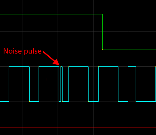
The points in between missing teeth on a 36-1, 60-2, or similar trigger wheel can use the same troubleshooting methods outlined for a distributor. But there are several specific issues that hit right at the missing tooth. One of the most common is a noise pulse right in the middle of the missing tooth, breaking the bar at the missing tooth into two half-height bars. With one missing tooth, this looks the same as the regular pulses. This example shows a 36-1 pattern having a noise pulse arrive at the missing tooth.

If all the missing tooth bars are broken in half, such as the log below with a 36-2 trigger wheel, it is likely you either have the sensor wired backwards or the Ignition Input Capture (Rising Edge or Falling Edge) set backwards.

Correcting this setting fixed the problem, as shown in this log from the same engine.

This shows up most frequently with VR sensors. If this happens on a MicroSquirt or MS3Pro ECU with a VR sensor, try a 10K resistor in parallel with the crank sensor, and decrease the resistance if that isn't enough to prevent the noise. For the V3.0 and V3.57 boards, try a 10K resistor in series with the crank sensor, and adjust the VR trim pots.
Tooth logs with irregular trigger wheels
It's easiest to understand a tooth log with equally spaced teeth, maybe with gaps one or two teeth wide. More complicated patterns can be a bit harder to envision. Perhaps the best way is to look at the physical distance between each teeth. The height of the bars is proportional to the distance. Here is an example with a GM 7X trigger wheel spacing being mapped to its tooth log.

Composite logs
The first thing to do when interpreting a composite log is to figure out how the trigger pattern relates to what pattern you should expect to see. You can envision what the pattern should look like by imagining unwinding the crank trigger into a straight line and making this into a repeating pattern. Here is an example using a GM 7X crank trigger.

Here is another example, showing how the teeth on a '99-'05 Mazda Miata crank and cam trigger compare to a composite log from one of these cars. The arrows show how the teeth on the triggers match to points in the composite log. Remember, you get two revolutions of the crank wheel for each revolution of the cam wheel. This diagram only shows one rotation of the crank trigger matched to its set of pulses.

Thin lines or square wave?
You'll notice that some composite logs will show only thin spikes, while others show a square wave pattern. This depends on whether the ECU is only checking one edge of the incoming signal or both. There are a number of settings that determine how many edges the signal uses.
- Certain spark modes, such as the LS1 decoder, always use both the rising and falling edges. Typically spark modes with this feature are built around using a Hall effect or optical sensor, and require checking the length of the teeth for cylinder identification.
- Turning on the noise filter will always cause the MegaSquirt to check both edges of a signal for the sensor where you have enabled noise filtering.
- If the spark mode does not require checking both edges and noise filtering is off, the MegaSquirt will just use one edge and display the thin spike pattern.
Look for the loss of sync
The red sync loss flag is a very helpful tool when viewing composite logs. The MegaSquirt will start off without sync and only change to indicating sync once it has read enough teeth in the correct pattern to determine the engine position. The MegaSquirt also will not report sync if it is in a diagnostic spark mode such as "Log Crank" or "Log Crank and Cam". But if the red bars appear in the middle of a composite log, you will want to start looking for the problem at the point where the red lines appear, and work backwards. The problem may occur right at the pulse where the red lines appear, or it may be up to two crank rotations earlier. This example shows a loss of sync on a 36-1 crank trigger, nearly one complete engine rotation before the lost sync flag appears.

Sometimes a noise problem does not result in a sync loss indicator, particularly if the ECU is able to use other rules to recognize the false triggering and reject it.
Noise pulses in composite logs
With tooth logs, you can identify noise by the height of the bars, but with composite logs, you use their spacing. If you can capture several crank rotations with a good signal, you can see what the pattern should look like. Then look for pulses added when they shouldn't be, or pulses not read where they normally would go. This Honda RC51 pattern log has a crank trigger with 12 equally spaced teeth. This shows up as equal spacing between the cam pulses. A noise pulse shows up as two closely spaced pulses, an exception to the rule.

Cam and crank signal misalignment
Some RPM input issues can occur when the cam position sensor occurs at the wrong time relative to the crankshaft position sensor. This can be a mechanical misalignment, such as a timing belt installed one tooth off. Or it can be a settings issue where the ignition input capture or second trigger active edge is set incorrectly.
The settings issue is an especially easy mistake to make on Nippondenso trigger setups that use a 24 tooth cam wheel (or 12 tooth crank wheel) wired to the primary input combined with a one tooth cam wheel. This picture shows the cam pulse arriving at almost the exact same time as the crank pulse, and the ECU losing sync.

When this happens, the ECU reads all the cam and crank pulses, but it sometimes reads the cam pulse before the crank pulse and sometimes reads it after. This can cause the ECU to read 23, 24, or 25 pulses in between the cam pulses. When this happens, the ECU is unable to accurately determine which is the correct #1 tooth, and loses sync.
In extreme cases, the crank and cam pulse arrive so close together the ECU is not able to correctly resolve that both have occurred. This will look as if you the ECU has missed a cam pulse.

When this occurs, you may need to try all four combinations of ignition input capture and second trigger active edge (falling or rising edge). Often the ECU will only run correctly across the rev range on one or two of the four possible combinations.

Note that you will need to confirm the tooth #1 angle with a timing light after changing these settings.
When serial noise disrupts a composite log
Sometimes TunerStudio may lose the serial data in the middle of a composite log. MegaLogViewer will attempt to flag these and report a gap in the data:

Occasionally, this gap in the data will generate a page that MegaLogViewer is unable to display correctly at all. Sometimes clicking the Options button and checking "Render including non interrupt data" will help; other times it just results in the page displaying incorrectly in a different way.

Typically, these unreadable pages are a result of serial data problems and not the cam or crank trigger. However, sometimes bad crank or cam trigger data can cause a misfire that causes serial data problem. If you run into a page that does not display correctly, you can generally ignore any pages that do not show a sync loss. If the only pages that show a loss of sync are incorrectly rendered pages, look for the yellow dots on the lines; they will indicate the location of sensor pulses.

Ideally, if this happens, you'll want to capture another log.
Once you've found the problem, now what?
Noise pulses and failing to read teeth can represent slightly different problems, with different solutions. There are several things to check in either case. Some of these may depend on the sensor type - VR, Hall effect, or optical.
If you are able to get an oscilloscope, that can be very helpful in viewing the nature of the sensor problem. These lists show factors you can check if you do not have an oscilloscope available.
Noise pulses
When the ECU reports pulses that didn't really happen, there are several things to check. Here are some of the more common causes.
Any sensor type
- Vibration in sensor mounting bracket, particularly if this is a retrofit trigger wheel installation
- Sensor gap too close
- Grounding problems with ECU or sensor
- Spark plug wires damaged or too close to sensor wires
- Nicked teeth on trigger wheel
- Try software noise filtering.
- If running non-resistor spark plugs, try changing to resistor type.
VR sensors
- MS3Pro or MicroSquirt
- Install a 10K resistor in parallel with the sensor.
- For low tooth count cam triggers with noise issues while cranking (Nippondenso CAS or Subaru 6/7 are common examples), use an AXM-120 VR conditioner.
- MegaSquirt V3.0 or V3.57
- Install a 10K resistor between sensor and input pin.
- Try adjusting VR trim pots.
Hall effect sensors
- Pull up resistor needed
- If running on 5 volt power, try 12 volt.
Triggering from an ignition coil
This is one of the most potentially noisy RPM input sources you can use.
- Make sure you are using an optoisolated input. If your ECU does not have one, use our AXM-110 isolator module.
- Try a 24 volt zener diode inline with the input, with the banded end pointed toward the coil.
LS1 type 24X crank triggers
These use an unusual design with a split crank trigger wheel. These can have noise or missed pulses if the clutch throw-out bearing is worn or the two halves of the trigger wheel have slipped relative to each other. This often results in very thin noise pulses near the edge of the trigger, as shown.

Missed pulses
When the ECU does not resolve a real pulse, many of the checks are similar, but you may need to increase sensitivity instead of decreasing it.
Troubleshooting: Any sensor type
- Vibration in sensor mounting bracket, particularly if this is a retrofit trigger wheel installation
- Sensor gap too far away
- Nicked teeth on trigger wheel
- Software noise filtering rejecting real pulses
- Trigger wheel run-out
- Sensor failure - particularly if the problem happens only with the sensor cold or warm
- Sensor wired through heavily filtered input such as an optoisolated trigger circuit
Troubleshooting: VR sensors
- If the cam sensor is dropping out and lines up very closely with the crank sensor, change ignition input capture and/or second trigger active edge.
- MegaSquirt V3.0 or V3.57: Try adjusting VR trim pots.
Troubleshooting: Hall effect sensors
- Pull up resistor too large
- If running on 5 volt power, try 12 volt