There are a few different MegaSquirt wiring diagrams floating around the internet. For the most part, they’re all the same. However some vary in regards to ground pin locations on the MegaSquirt DB37 connector. Proper grounding is one of the keys to a successful installation of any EFI system, so we want to help remove any confusion. This article addresses discrepancies in the ground schemes across diagrams in order to remove any confusion and help ensure a successful installation.
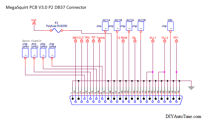
The MegaSquirt’s DB37 (main) connector has 37 total pins, hence the designation 37 in its name. However 15 of these pins are internally connected to the MegaSquirt’s ground plane, and therefor 22 have non ground functions. We recommend using only 5 out of the 15 linked pins available for grounding the MegaSquirt to the engine. Largely it does not matter which of the 5 pins you select. As MegaSquirt diagrams have been drawn by different people at different times, various ground schemes have been shown.
The schematic below shows how the MegaSquirt “P2” connector (the DB37) is routed internally. As you can see, the following pins (as shown with black designators) are all connected to the ground plane: Pins 1, 2, 7-19
The current version of the DIYAutoTune.com Preassembled Wiring Harnesses come pre-pinned with the following ground scheme:
High Current Ground: pins 15-19
Sensor Return: pin 7
VR-: pin 1
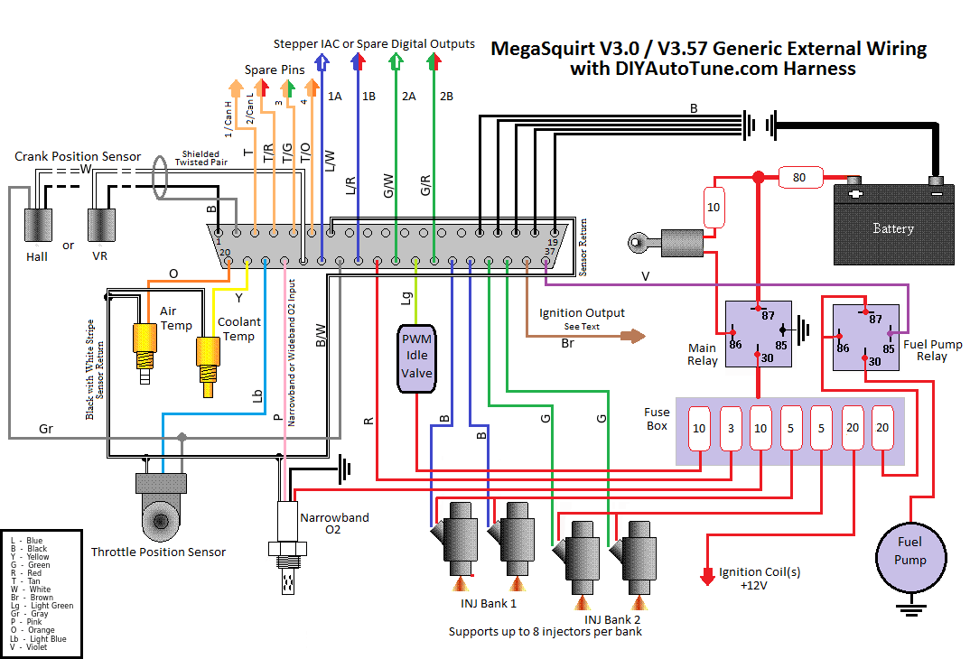
The DIYAutoTune.com Harness is pinned correctly for use with your MegaSquirt. The ground scheme may be different than what is shown in some documentation, however as described in this article, this is not problematic.
What is important is not which pin numbers are used to ground the MegaSquirt so much as wiring the grounds in a correct manner directly to the engine (directly to block or head, not to valve cover) or battery. As a general rule, grounding to the body, frame, or firewall is not suitable. Grounds must be made on clean, rust-free bare metal free of paint, powdercoat or anodizing. The mechanical connection must be tight and solid. Any crimp connections must be tight. Any solder joints must be flowed properly, shiny in color, and clean.