Assembly
Assembling the JimStimX is very straight forward, and is a perfect first time project for someone who is new to the world of soldering and/or MegaSquirt assembly.
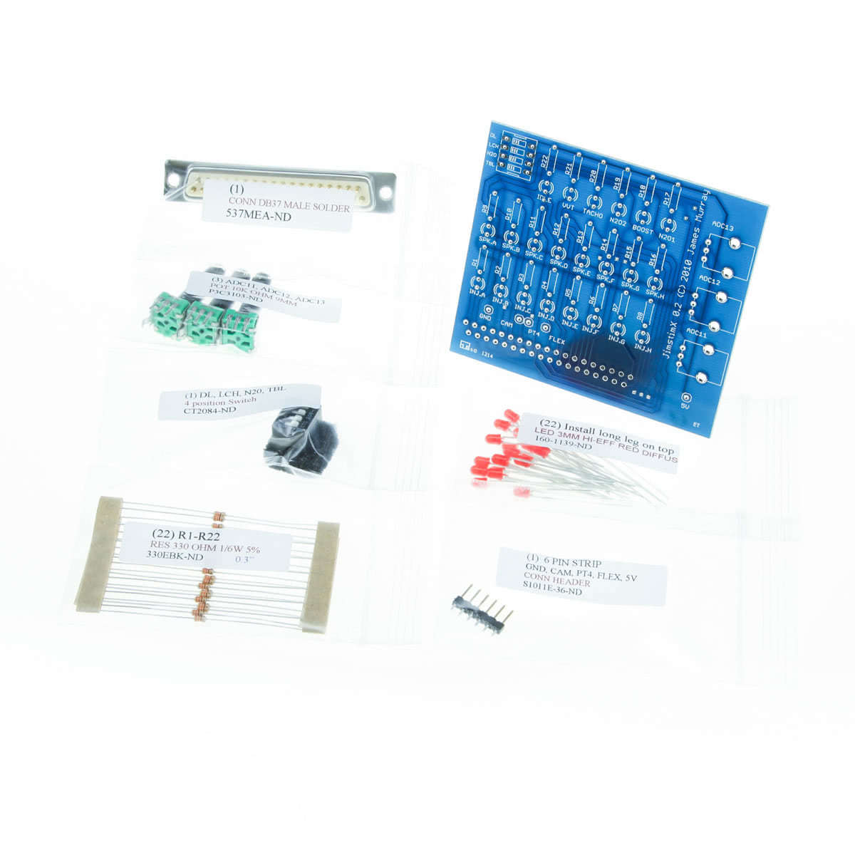
The concept is simple. Start with the shortest components and work up to the tallest. Estimated project time should be around 30 minutes. We recommend using 63/37 tin/lead solder. The newer lead free solder types are much harder to work with and not as reliable.
1) The first set of components to install will be the resistors, labeled R1 to R22 on the board. All of the resistors are the same, and polarity is not important so they can go either way. Install all 22 resistors, then turn the board upside down and solder all the resistors in place, and clip the excess leads.
2) The LEDs are next. There are 22 of these as well. One installs underneath each resistor installed in the previous step. Pay close attention to install the LEDs with the longer leg towards the top of the JimStimX board. Polarity is very important with the LEDs; they will not work if installed backwards! After installing, turn the board over, solder all the connections, and clip the lead excess off.
3) The next tallest component is the 4 position switch at the top right of the board. Go ahead and install it now. Note the silkcreen indicates the orientation of the switchblock with the switches in the off position. It solders from underneath the board.
4) Now we install the header pins near the bottom of the board for the ground, cam sensor, PT4, flex, and 5V connections. They will come on a single strip, so you will need to carefully cut the pins along the indented break points on the strip. They will cut easily with a wire cutter or similar tool. Cut to size and solder from underneath.
5) Now we’re up to the very tall components, which are the ADC trim pot assemblies. They install on the front of the board. Make sure you line up the metal tabs on the sides of each trim pot as well as the 3 legs with the corresponding pads in the board. You can solder one of the metal tabs on each pot from the top to hold the trim pot in place if you’d like. This is not required, but makes it easier to flip the JimStimX board upside down before soldering the legs in place, as it keeps the trim pots secure.
6) One item left: the DB37 connector. It installs on the bottom of the board, on the back side. It solders from the front side of the board. Make sure you install it on the correct side. See the pictures for clarification if you have any doubt.
The board is now completely assembled and ready for use!
Usage
The JimStimX is very simple to use. It connects to your MS3X EMS on the Expander connector. You will also need to connect a JimStim on the MS3X lower/main connector. You must connect 5V from the JimStim (available on the pin header, pin #26) to the 5V header pin on the JimStimX to power the LEDs. If you do not connect a 5V jumper, the JimStimX LEDs will not light! If you have a second tach input, you can connect a second jumper from the JimStim’s 2nd trigger output to the cam header pin on the StimX. There are also header pin connections for ground, pt4, and flex fuel inputs for testing of various functions.
Digital inputs datalog in, launch, nitrous, and table switch can be tested with the switches on the top left of the StimX board. Note the arrow on the switch facing the inside of the board. Moving the switches to the inside/right of the board in the direction of the arrow connects the switch to ground. Moving the switch back the left/outside of the board, away from the direction of the arrow causes the input to float.
The large trim pots on the right can be used to simulate 0-5V analog signals (such as MAP sensor, wideband o2, or other sensor signals) on ADC inputs 11, 12, and 13.
