Sequential Injection
The MS2/Extra 3.0.3 and higher code allows for 4 channel sequential injection with a DIYPNP. This can run sequential injection on a 4 cylinder, or semi-sequential on a 6 or 8. To use this, you’ll need our DP_SEQMOD-K add on board. It attaches to the proto area with the included 10 pin header; just solder the header in place and run the two injector outputs over to the adapter board. Install it so the two injector driver transistors are pointed out over the proto area. For low impedance injectors, ground the GND hole on the adapter board to a GND hole on the main board (do not connect to SG).
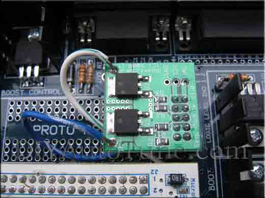
The above picture shows one installed. Note that it covers a portion of the proto area.
The injectors are numbered by their firing order and fire in a 1-2-3-4 sequence, so you’ll need to jumper this to the adapter board according to the engine’s firing order. For example, you’ll connect the injector outputs as follows for a typical inline four cylinder engine with a 1-3-4-2 firing order.
Main board INJ1: Cylinder 1
Main board INJ2: Cylinder 3
Expansion board INJ3: Cylinder 4
Expansion board INJ4: Cylinder 2
Now, you just enable sequential in software, and tune the settings. This is done in the ‘Advanced > Sequential Injection’ menu. There’s really not much to ‘tune’ here unless you’re just dying to tune something. You really only need to set a few base settings and then just let it rip. These settings were used on a ’99 Miata running sequential injection:
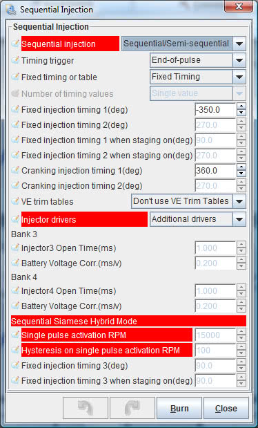
These settings are tuned to squirt at the intake valve opening during cranking, and 10 degrees before it opens while running.
The sequential code also allows you to use a timing table to control the injector timing as a function of RPM and load, and four individual injector trim tables. These can be accessed in spreadsheet form under the Advanced menu, or as 3D maps on the Tuning menu. For more information about the sequential code, follow this link. The DIYPNP avoids the need for hardware mods shown in that link that a normal MS2 would require, as the processor outputs are brought out directly to the DIYPNP’s 10 pin header.