“Foonix” on the Club 4AGE forum sent us a link on Club4ag (now offline) where he’d managed to alter a Zeal Engineering daughterboard to drive a 3 wire IAC valve. We’re reprinting his tips here, with his permission.
After looking to build the IAC circuit in this thread, I realized it could be built without using the prototyping area by modifying the Zeal board slightly. My version uses the PWM idle setup on the megasquirt v3, the PWM idle output on the Zeal board, and an unused relay control from the Zeal board as a signal inverter. The MS built-in fast idle circuit is used to form the opening circuit (RSO), and the Zeal board forms the closing circuit (RSC). I’ve tested this on my car and so far so good.
Using IRF540 or TIP120’s for the 4AGE 20v IAC seems to be overkill. The IAC should pull just under 1A per side. The MS’s built in f-idle transistor is rated for 1A, so we just need an uprated transistor for more overhead. A ZTX688B-ND like the one that comes with the Zeal board is 3 amp and has the same pinout, so it should work as a drop-in replacement. I used a VB921 just because it is what I had laying around. [VB921s have been discontinued for several years; you don’t need to go looking for one if you don’t already have one handy – ed.]
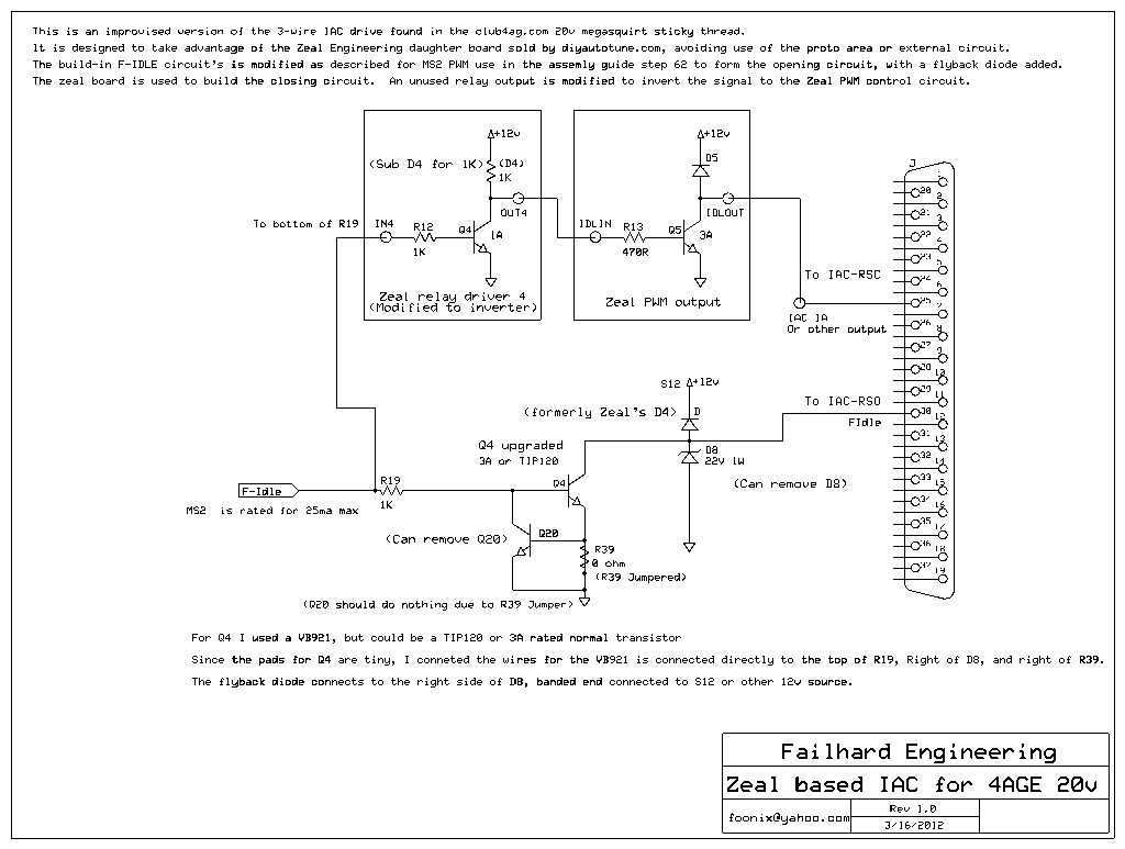
Here is the circuit diagram:
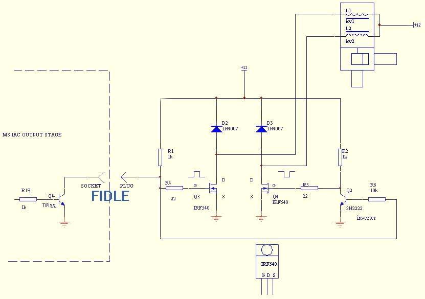
For comparison, here is the original:
What is needed:
- The Zeal Engineering megasquirt daughter board
- An additional 1k resistor.
- A diode to add to the megasquirt’s built in PWM idle circuit. A diode (1N4001DICT-ND) will be removed from the zeal board and can be recycled for this.
- A spare output on the MS harness chosen to become the closing circuit.
- An uprated transistor to replace Q4 on the MS. A TIP120 is overkill (but OK). A ZTX688B-ND should work and drop straight in.
Building the circuit:
- On the Zeal board, pick an unused relay output and remove its diode. For this guide, we’ll use IN4/OUT4, which uses D4.
- Replace the removed diode with a 1k resistor.
- On the MS, modify the board for PWM idle according to the MS2/V3.0 Hardware manual at MSExtra.com
- Remove Q20 and D8 (optional?)
- Remove R39 and replace it with a jumper.
- Replace Q4 as discussed.
- Solder the non-banded end of a diode to the right side of D8, where the banded end of D8 was previously. Solder (using a jumper wire if desired) the banded end to S12, which is a 12v power source nearby, or any other 12v power source. It may be easier to do this on the bottom of the board. The diode removed from the zeal board can be used for this step. Note this diode does not fully replace D8, I.E. do not connect the banded end to the left pin of the D8 slot.
- Solder a jumper wire from the bottom of R19 on the MS to IN4 on the Zeal board.
- Solder a jumper wire from OUT4 to IDLIN.
- Solder a jumper wire from IDLOUT on the zeal board to an output of your choosing. I used IAC 1A, which corresponds to pin 25 in the harness. Any IAC or SPR pin should work.
External wiring:
- Wire the B/W (RSC, “left” pin) wire on the IAC to the harness pin chosen in the previous step (IAC1A = pin 25).
- Wire the B/L (RSO, “right” pin) wire on the IAC to pin 30 on the harness (F-Idle)
- Wire the B wire (+B, “center” pin) to a 12v power source controlled via relay. This should probably be a relay controlled by the fuel pump relay to prevent the IAC from running while the engine is stopped but the key in “run.” Running off the same relay as the injectors/coils should also work.
Some notes:
- It will NOT idle with the IAC in the fully closed position. For initial startup testing, try setting the Algorithm to “On/Off” and the temperature high enough to force fast idle ON.
- If using the ITB mode code, the PWM idle setting changes may muck with the “ITB load TPS switchpoints” graph, and may need retuned.
- The default PWM settings cause the IAC to moan. The frequency probably needs adjusting.

