- Adding a second wideband o2 sensor to the MegaSquirt-II
2. Adding an relay control circuit to the MegaSquirt PCB-3
3. Adding a ‘Pullup Resistor’ to the ignition input
Adding a second wideband o2 sensor to the MegaSquirt-II
If you’re running an engine with true dual exhausts, you could use a single wideband sensor for both banks. Or since the Megasquirt has two independent injector outputs, you could modify the ECU so it reads a separate O2 sensor for each bank and correct for the two banks separately. Doing this requires that you have all the injectors on one bank wired to one injector output, and all the injectors on the other wired to the opposite output.
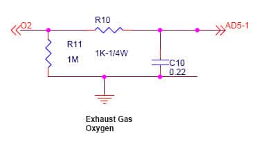
This requires a pretty minor mod. You’d need to duplicate the o2 input circuit on the main o2 input, it’s only 3 components and could easily be built on the proto area of the v3 PCB. The Input is labeled O2′ below and could go to Jmp SPR1′ on the PCB which would bring it out to pin3 so you could wire the o2 sensor there. The output to the MS2 CPU is labeled AD5-1′ below and would be routed to JS5′ on the PCB which would route it to the proper pin on the CPU. That should be all it takes.
Adding an relay control circuit to the MegaSquirt PCB-3
Great for Megaquirt-I, PCB3 units with MSnS_E code. For MS-II units with firmware version 2.3 or later you don’t need to mod anything! Use the FIDLE output on pin 30, or the stepper IAC outputs.
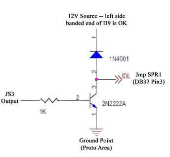
This is one example of what you can do, in this example I used the JS3 output from the MS-I CPU as the input into this circuit (telling it when to switch on/off) and the output routes to Jmp SPR1 which sends the signal out to the DB37 on pin3 which is a pretty good choice since on the v3 it’s not used for anything else. You’d then use pin3 on the DB37 to control your relay which controls your electronic doodad of choice — shift light? electronic fan? variable intake system such as Toyota TVIS? Honda VTEC? EZ Bake Oven? Whatever you want….
The outputs you can use depend on the Megasquirt type you have. Here is a list of outputs that use this circuit.
| MS-I V3.0 / V3.57 | MS-II V3.0 / V3.57 | ||
| Output 1 | JS2 | Injector LED | Top of R26 or U1 pin 7 |
| Output 2 | JS3 | Accel LED | Top of R29 or U1 pin 8 |
| Output 3 | U1 pin 15 / JS12 (remove R1) | Warm-up LED | Top of R27 or U1 pin 9 |
| Output 4 | Top of R27 or U1 pin 9 | Knock Enable | JS11 |
| MS-I V2.2 | MS-II V2.2 | ||
| Output 1 | X4 | Injector LED | Top of R25 or U1 pin 7 |
| Output 2 | X5 | Accel LED | Top of R28 or U1 pin 8 |
| Output 3 | U1 pin 15 (remove R14) | Warm-up LED | Top of R26 or U1 pin 9 |
| Output 4 | Top of R26 or U1 pin 9 | Knock Enable | JP1 pin 4 |
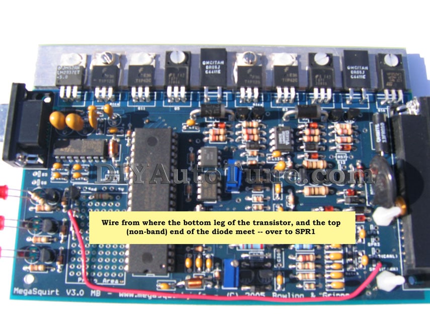
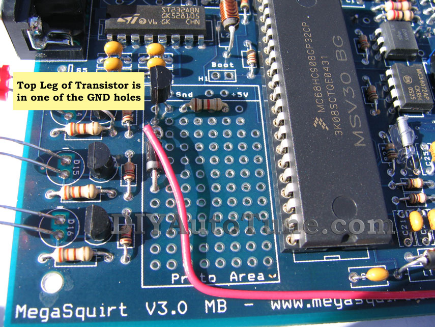
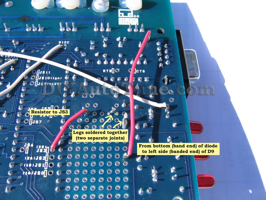
Here are some pictures on this mod performed on the V3 board. (Red wires are this mod, ignore the white)
Adding a ‘Pullup Resistor’ to the ignition input
PCBv3.0 Boards, MS-I or MS-II
Hall effect and optical sensors come in several varieties. Some send out a square wave signal on their own, going from 0 volts to 12 (or sometimes 5) volts and back to zero again. Others are what’s known as an open collector. An open collector signal works kind of like an electronic version of a set of breaker points. It toggles between floating (acting like it’s not connected to anything) and ground. If you put a volt meter on an open collector output, you won’t see anything happening. It would be like replacing the sensor with a light switch with one end connected to the MS tach input and the other end connected to ground: When the switch closes, the input is at zero volts, but when it’s open the input is not connected to anything at all, and with the normal circuit that is pretty much the same as zero volts again. To get a useable, voltage based signal, you’ll need what is known as a pull up resistor. VR sensors always put out an AC signal when the engine is running and do not need this mod.
A 1k (1000 ohms) 1/4 watt resistor is what you want.
Solder one end to the right side (non-band) end of D1, and solder a small piece of wire to the other end, heatshrink tube the resistor and solder joint to protect it, and solder the other end of the wire to the left leg (banded end) of D9. The left/right references are when looking down at the top of the board so that you can normally read the text, though you will probably do this mod on the bottom of the PCB…
Alternately… you can do this in your harness. Use the same resistor, hook one leg up to the wire connected to pin 24 (inner conductor only if you’re using shielded wire) and hook the other end up to a 12v source, like the wire connected to pin 28, the main MS power wire. This harness method works for PCB2.2 or PCB3.0 boards. Heatshrink tube everything up nicely to protect your wiring, and maybe tape this resistor up in the wiring to keep it from getting bent up alot as you don’t want that connection to break, and the resistor leads could get brittle if they get bent much.