Your VVTuner CCM module will provide years of consistent and reliable operation if care is used during its handling and installation. The hardware is designed to work within the environment found within the interior of the typical automobile and the rugged applications that may be experienced. However, the controller is an electronic device that is sensitive to moisture, shock, and static discharge. Heeding the installation instructions and recommendations will guarantee the operation and reliability of the VVTuner CCM.
MAP sensor
The VVTuner CCM has a built in MAP sensor. This is a 2.5 bar unit that reads up to 21 psi of boost. Plumb it to a vacuum port on the intake manifold plenum. The best location is usually to tee the signal off the vacuum line to the fuel pressure regulator.
Crankshaft Trigger Wheel
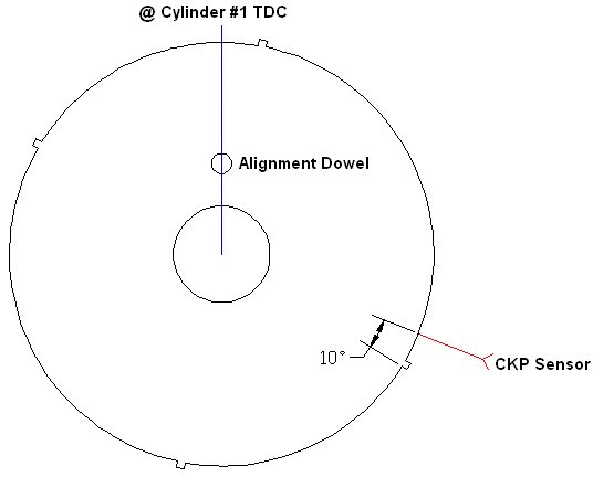
The crank shaft trigger wheel can easily be installed incorrectly. If you have removed the crank pulley or trigger wheel, verify the trigger wheel installation as depicted below. When installing the wheel, ensure that the center outward bevel is against the accessory pulley. If the wheel is installed backwards, a low or otherwise incorrect RPM value will be displayed in MyVVT. The VVTuner does not support non-factory trigger wheels such as the Flyin’ Miata 36-2 design.
Figure 1: Crank Trigger Wheel
General Wiring Considerations
All connections should be soldered for optimal results. Using low quality crimp on connectors or “wire stabs” will ultimately lead to an unreliable or failed connection. Use heat shrink tubing or quality electrical tape (I.E. 3M 33+) to protect all taps and splices. Solid conductor wire should be avoided at all costs as vibration will eventually fatigue and damage the conductor. Instead, you should only use stranded wire that is rated for a minimum of 90 degrees Celsius and is oil and gasoline resistant, such as TXL or equivalent marine / mil-spec wiring.
Power Source: Selecting a power source is critical to reliable operation of the VVTuner system. Observe the following procedures when selecting a 12 Volt power source:
- Connect the positive supply voltage to a switched circuit that is powered both while the vehicle is being cranked and running.
- Ensure that the selected power source can supply ample current to the VVTuner CCM if tapping an existing source.
- If the unit will have a dedicated circuit, it shall be protected with a fuse no larger than 5 Amps.
- Use a wire size no smaller than 20 AWG.
Grounding: Grounding is important to ensure validation of the monitored signals. An ideal ground connection is either directly to the battery or to the engine. We do not recommend the use of “vampire taps” or grounding directly to the chassis.
Wiring Connections
Ground Selection: When connecting the sensor grounds, the ideal connection point is directly to the VVTuner CCM (Fig. 2). This will assist in preventing noise from being induced into the system. However, circumstances may be such that the method displayed in Figure 2 may not be possible (I.E. the use of factory wiring) and, therefore, you may have to use the methods in Figure 3 instead.
Trigger Output Wiring to EMS (Optional): If wiring connections are to be made to an EMS, pin 9 on the VVTuner CCM connector must be connected. By default, the trigger output signal’s ground is isolated from the system ground. Ideally, pin 9 should be connected directly to the EMS’s ground source. This will minimize noise induction on the trigger signals. Figure 3 depicts such a ground connection.
If the VVTuner CCM and EMS share the same ground or a direct ground to the EMS is undesirable, pins 9 and 10 can be connected together either by way of a short piece of wire or a solder bridge between the two pins.
Shielding: If the wires are run for more than 3 feet (1 meter) or run through the engine compartment, we recommend shielding the wires to the CKP and CMP sensors, as well as the signal wires running from the VVTuner CCM to the EMS. The shield should be grounded to the VVTuner CCM but not at the other end, to avoid ground loops. For short runs of wiring inside the passenger compartment, the shielding may be omitted.
Figure 2:
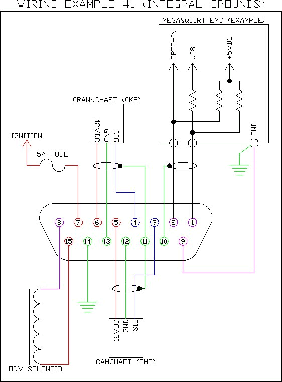
Figure 3:

Sensor Connections: When connecting the crankshaft and camshaft trigger sensors to the VVTuner CCM, observe the diagram found in Figure 4. The images shown are viewed from the open end of the connector found on the engine wiring harness. Ensure that the connectors are properly wired as damage to the sensors can occur if wired incorrectly.
Figure 4:
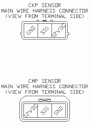
Figure 5:
Mounting
Do not mount the VVTuner CCM within the engine compartment of the vehicle. The enclosure is neither sealed nor protected from the harmful environment that is found under the hood of a car. The controller must be securely mounted to a bulkhead-like structure in a way that significant vibration is eliminated.
Instead, mount the VVTuner CCM within the vehicle’s cabin area. Furthermore, locate the controller in such a location that neither the driver or passenger are likely to accidentally hit the module. Good locations include behind the seat or under the ECU cover panel on 1.6 models, somewhere a passenger isn’t likely to hit even if flailing around in a panic because you got on the brakes too late on the back stretch of Road Atlanta. Wiring and vacuum hoses must be routed so that it will not come into contact with any moving parts such as pedal assemblies or heater/AC controls. That hole in the firewall near the clutch pedal, for example, looks easy to use, but any vacuum line through it is easy to pinch.