Updated September 2022 by Jerry Hoffmann
Chapter 2: Why should you convert to Electronic Ignition Control? And what is a timing table?
Timing Tables and Advance Curves in a modern electronic ignition system versus the old school distributor and mechanical/vacuum advance. What’s better and why? That is the question.
I’m going to do you a favor if you just read my intro to Electronic Fuel Injection and skip some of the details I offered there, as to be honest, many of the same principles apply to Electronic Ignition Control and it would seem repetitive. The Tables you tune, and the tools you use to do so, are almost exactly the same in how they look and function. In this case we’re managing the Ignition Advance, aka Ignition Timing, aka Ignition Advance and Retard, with absolute precision. But the Tables you tune, and the tools you use, again are almost exactly the same. So the things you’ve learned in the prior chapter will apply here as well!
Inputs and Outputs – those can be sortof scary words I suppose. Let me simplify that for you– we’re speaking in regards to the ECU. What would the inputs be? The sensors!! That’s right. They bring information INTO (input) the ECU. It’s that simple. The ECU just needs information from a handful of sensors so it can know what’s going on with the engine. That’s all we mean if we use the word ‘inputs’. Outputs– similarly, still in regards to the ECU, this is what is coming OUT of the ECU, aka outputs. Control of fuel injectors, ignition coils, solenoids and relays– those are all outputs. Don’t let those words confuse you or give you flashbacks of Johnny-5 in the movie Short Circuit. Ok, it’s OK if it makes you think of the movie.
Bottom line– An input is information the ECU is gathering in order to decide how to control things. An output is something the ECU controls like an injector or coil. It’s that simple.
We’ll talk about some of the different types of ignitions systems, including the sensors (inputs) required like the crank angle sensor and cam angle sensor (aka Crankshaft Position Sensor and Camshaft Position Sensor) that tell the ECU not only the engine speed in RPM, but also the EXACT location in the engine’s cycle, whether that is a 360 degree cycle of a 2-stroke, or the 720 degree cycle of a 4-stroke engine. Then on the ignition coil/spark side of things (outputs), we’ll talk in detail about the different types of ignition systems to fire that spark, and fire that spark with the maximum energy, or in some cases the most efficient energy, needed to get the most out of your engine. From a single cylinder engine with a single coil (yes we can run a go cart or lawnmower or generator engine if you’d like!), to a 2cyl, 3 cyl, 4,cyl, 5, 6, or 8 cylinder engine, or more! (We can control 12 easily) with a distributor and single coil, or a wasted spark engine with a coil per pair of cylinders firing two per engine cycle giving you more time to dwell/charge the ignition coils for increased spark energy at high RPMs, or the ultimate—a full coil on plug or coil per plug conversion using a dedicated ignition coil for each cylinder, running sequentially meaning it only fires once per engine cycle giving it maximum time to dwell/charge that coil to REALLY light the fire no matter how high of a compression ratio or forced induction boost you’re feeding that engine. If it’s a spark ignited engine, we can control the timing of that spark. Electronic Ignition Control with a ECU such at the MS3Pro will give you all of this control, and a whole lot more.
I won’t go into all of the engine safeties again (See Chapter 1 of this series for full overview of MS3Pro Engine Safeties), but yes, several of them are ignition related and/or use the fact that you’re controlling the ignition on your engine to save the day if something goes awry and ignition retard, or even cut, is needed to protect your engine.
So give me the quick and dirty– what makes Electronic Ignition better than a mechanical distributor?
Several things. Here are a few to get us started.
Benefit 1: Ignition Advance/Timing Accuracy
The Problem
A distributor, and it’s chain of mechanical dependencies from the timing chain and crank/cam gears it turns on, to the camshaft, to the meshing of the gears between the camshaft and the distributor shaft and the shaft itself, to the rotor button and cap, slop in the points. At every step along the way, some small amount, or in some cases a larger amount, of mechanical ‘instability’ is introduced. You’ve seen this before when you put your timing light on a mechanical advance distributor based engine, you just likely accepted it as normal. And maybe since it’s normal, assumed it doesn’t matter. But it does.
This instability is caused by all sorts of mechanical phenomena as that engine rotates, and the camshaft that’s connected to the crankshaft via the timing chain spins as well, and the camshaft, at the other end with all sorts of forces acting on it via the lifters, turns a gear that connects the distributor shaft to the party, and that distributor shaft connects to the rotor button, with the cap overhead. Vibrations, sticking of the gears/chain, lifter/valvetrain wear or lubrication differences accounting for inconsistent forces on the different camshaft lobes, even in some cases twist introduced to the camshaft and/or distributor shafts themselves! It may not sound like a lot. It may not sound like it could matter. It does. And you can both make more power AND operate your engine more safely if this jitter/slop is eliminated.
Here let me show you… Go put a timing light on your mechanical distributor ignition system engine. Idle the engine as a speed that will keep the distributor commanding base ignition timing, maybe 10*BTDC for instance. Chances are you have a mark on your balancer/crank pulley at 10deg. Put your light on the balancer/crank pulley and watch that mark on the pulley/balancer in relation to the point or another reference mark on the engine that’s not spinning. Does it sit ROCK SOLID at 10*BTDC? Of course it doesn’t! It bounces around a little. Just a degree or two maybe, but it certainly is moving just a little bit. “THAT’S NORMAL” you would probably say. “It doesn’t matter.” “It’s just the way it is, that’s how it always looks.”
And you’d be right that “that is just the way it is”…. if that’s all you’ve ever known. That IS normal on a mechanical centrifugal advance distributor ignition vehicle. What makes it normal though, and does it matter at all? All that ‘slop’ I described above introduces a small amount of error. 1-3degBTDC in many cases, and yes, that matters. The gears, chains, shafts, and other mechanical interfaces that, combined– can easily introduce variability in the final ignition timing on each cylinder. You may have your distributor set to max out a 36*BTDC when the advance is ‘all in’ at 3000rpm and above like in the chart below. But with that mechanical ‘slop’ factored in, what your engine is actually seeing is somewhere between 34-38*BTDC!
But what if your engine makes best power right at 36*BTDC? That’s what you set it too right? At 34*BTDC you’re not making all the power you could be making. At 38*BTDC you’re risking detonation and engine damage. YOU WANT 36*BTDC, EVERY SINGLE TIME.
You’ll never get it. Not with a purely mechanical distributor. Even with quality, brand new components, properly installed and adjusted, you can of course reduce this ‘chatter’ or ‘slop’, but it’ll still be there. Furthermore, just the centrifugal adjustment mechanism of these old-school distributors introduces some chatter/slop/variability in the spark timing as the weights and springs try to perfectly control movement and ignition timing, but cannot.
There is a solution
Now… go put a timing light on a more modern vehicle. Say perhaps a 2000ish Camaro, or Corvette, or Chevy Truck, with one coil per cylinder. (I recommend these engines for this illustration as they still uses plug wires, making it easy to hook up a timing light – coil-on-plug systems require some creativity here). Now– Find (or make with a dab of whiteout) a timing mark on the crank pulley/balancer, preferably at around 0 or 10deg BTDC. And find a reference ‘pointer’, both of which are usually there from the factory in that era. Use the vehicle’s service manual and follow the procedure for checking ignition timing, this will allow you to ‘lock’ the commanded timing at a certain amount of advance. Now, put the timing light on the pulley/balancer and look at the timing marks in relation to the pointer. ROCK SOLID. No identifiable movement. The timing light fires at the exact same spot in engine rotation, every single time. Not within 1-2 degrees of the same spot. On the EXACT SAME SPOT, every single time.
This same accuracy is available with aftermarket standalone Engine Management if you set your ignition system up properly using the same tech that the OEMs use to accomplish this, and we’ll show you how in this guide.
Now… you want 36*BTDC? You command 36*BTDC. And you get 36*BTDC.
No more compromise, no more leaving power on the table or risking detonation. No more having to detune your ignition advance slightly in order to eliminate that risk of engine knock/detonation. Before, maybe the engine would have made more power at 38*BTDC instead of 36deg… BUT.. you couldn’t set it to 38deg BTDC because of the slop allowing it to sometimes hit 40deg instead! Now you can! Now that the slop is eliminated, you can command 38deg and KNOW that it will get 38deg. Make ALL of the power the engine is capable of making, and eliminate the risk of damage.
So what makes this possible? I mentioned looking for a vehicle with one coil per cylinder. The multiple coils are not the solution, but they are indicative that the solution is there. The root of the problem is not the output side, the ignition coils – the root of the problem is the INPUT side. What the engine is TRIGGERING off of to tell the spark when to fire. On a on a classic vehicle with a mechanical distributor, this is the cam on the points
Computer Controlled Electronic Ignition using a Crank Trigger is the answer here. Even if you’re still using a distributor for the OUTPUT of the spark to the ignition coils, so long the INPUT side, the side telling the, in this case ECU, where the engine is in it’s 720deg rotation cycle (on a 4-stroke), then the ECU can fire that spark with the utmost of precision. And that ignition timing jitter? It’ll be gone. More on this in a later chapter!
Benefit 2: Tunability and Control of Ignition Advance Timing Tables
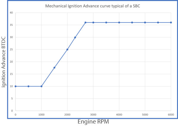
If you’ve ever dialed in the weights and springs on a classic car’s centrifugal advance distributor, you may be familiar with the below chart. This happens to be a common advance curve for a centrifugal/mechanical advance distributor in a SBC of BBC engine. 36 degrees ‘all in’ from about 2700 rpm up to redline. It works fairly good, considering it’s a technology developed ~100 years ago.
You can EASILY use a MegaSquirt, MS3Pro, or MicroSquirt ECU to EXACTLY replicate this same ignition advance curve, and for some of you, that will be a good place to start! Check the below timing table out that does exactly that!
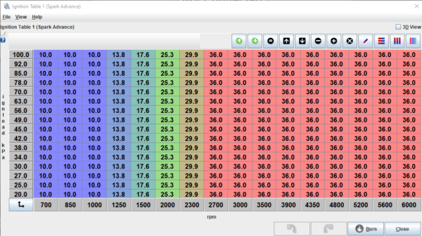
Now– Compare that Ignition Timing Table to this Centrifugal Advance Distributor Image just above it. Look at the bottom left of the MegaSquirt Ignition Timing Table, for now, ignoring the ‘Y Axis’ which is the vertical axis on the left marked ‘IgnLoad kPa’. You’re only looking at the horizontal ‘X Axis’ showing RPM at the bottom. (The centrifugal advance curve shows Ignition Advance on that axis, instead of engine load)
In both images, you can see that at 1000rpm and below, you get 10*BTDC of ignition timing. Then at 2700rpm, your ignition advance is ‘all in’ at 36*BTDC, and it stays that way all the way to the 6000rpm redline. In between 1000rpm and 2700rpm, as the ignition advance ‘comes in’ the advance ramps up from 10*BTDC to 36*BTDC.
If you were to use the Ignition Advance Table pictured above in your MegaSquirt or MS3Pro ECU on your Small or Big Block Chevy Engine, you would be running the EXACT SAME ignition advance as you would with the centrifugal advance distributor by adjusting springs and weights to give you the results in the curve at the beginning of this section. The two curves are the same.
Vacuum Advance
OK, but my distributor is not just using a Centrifugal Advance, but also a Vacuum Advance! Bravo! Now you’re working with technology first put to use to further improve drivability, economy, and emissions in the 1950’s and 1960’s! And it is an advance (pun intended) in technology over running a purely centrifugal advance distributor!
Note: Vacuum is present in your intake manifold any time you are at idle or partial throttle where the throttle body isn't open enough to allow enough air to flow into the engine to match atmospheric pressure, because the engine is injecting air into the cylinders faster than the air can flow into the throttle body to replenish the intake manifold pressure. At Wide Open Throttle, typically the intake can draw enough air into the intake manifold to keep up with the demand of the engine, and you'll see zero or close to zero vacuum.
Vacuum Advance allows the distributor to further advance the distributor’s ignition advance curve at part throttle, when there is vacuum in the intake manifold. This is done to allow the engine to operate at MORE ignition advance/timing when the engine is at partial throttle, which gives benefit to emissions, fuel economy, and drivability.
Some vacuum advance distributors allow this to be tuned to a degree, but with limitations. Computerized Electronic Ignition Control using an ECU such as the MS3Pro, MSPNP or other MegaSquirt ECU variants we offer will allow you INFINITE control of the vacuum advance. And furthermore, it will allow you to RETARD the ignition advance under boost from the turbocharger or supercharger. The MORE pressure in the intake manifold, the LESS ignition timing your engine needs. Conversely the LESS pressure there is in the intake manifold, the MORE ignition timing your engine needs.
What does this look like in an MS3Pro/MegaSquirt Ignition Table? I’m glad you asked!
Now let me show you that SAME exact timing table, with the common areas of interest, that need different amounts of ignition advance for different operating conditions, marked so you have an idea of what you’re tuning, where, and why!
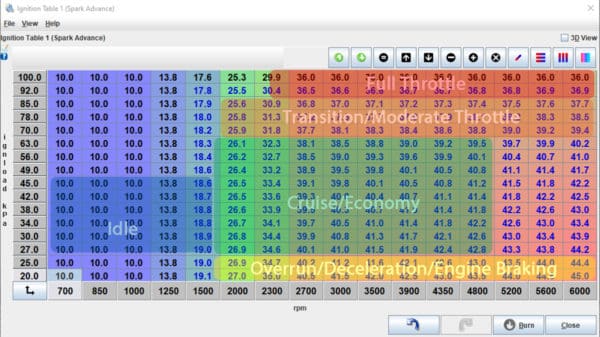
Tuning Ignition Advance to EXACTLY what the engine needs, at all loads/throttle positions (based on vacuum), and at all RPMs.
But you want to make power, right? All of the horsepower? Or just part of it? I know I want to make ALL OF THE HORSEPONIES!!!
What if, for your particular engine, it may be spot on perfect at 36degBTDC at 3000rpms and wide-open throttle…. but at 3500 rpms, perhaps your engine is reaching peak torque and 36degBTDC is just a little higher than ideal, perhaps 34degBTDC would be ideal there. But then at 4350rpms, it needs to be up to 37degBTDC. Then at 5200rpms, 38*BTDC makes the most power from there through redline? That’s another of the benefits of computer controlled ignition. You can dial in the ignition advance curve to fit the needs of the engine at ALL RPMS.
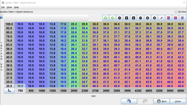
Not just based on RPMs, but on engine load as well! Engine load is usually presented as ‘manifold pressure’, aka vacuum. You may be used to thinking of this as ‘inches of vacuum’. And you can set your MS3Pro / MegaSquirt ECU up to give you a gauge that shows you that, but typically the ECU refers to this in kPa measurements. Generally speaking, 101.3kPa equals one ‘atmosphere’– that is, the air pressure at sea level. Unless you’re at a high elevation, you can generally think of roughly 100kPa as being atmospheric pressure. As a result of this, typically on a naturally aspirated engine (no turbo or supercharger boost increasing the pressure above atmospheric) you would use 100kPa as the top row in your tables when tuning your engine. Fuel tables, ignition timing tables, and any others. Like in this table below:
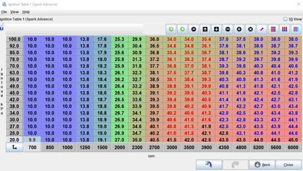
Nirvana… In this example, I’ve shown what your ignition advance table might look like once tuned for all loads and rpms to maximize it’s efficiency and power in all operating conditions. Take a moment and compare this timing table to the two tables (which are the same) above it, and note the differences and how they match the example I gave above regarding pulling some timing at peak torque, and ramping it back in (and then some) at high rpms. THIS IS HOW YOU MAXIMIZE YOUR POWER AS THE RPMS CLIMB. One number… 36*BTDC, is just not enough. You could be leaving 10, 20, 50, 100 horsepower on the table depending on your combo if you don’t optimize this as I’ve shown here. And not only that, you could be over-advancing your timing at critical areas, like under peak torque, and risking engine damage. Do it right and you get ALL of the benefits, without any negatives.
Note that I have given this example mostly in discussion of wide open throttle performance, but this ability to dial each cell into perfection is critical for maximum part throttle torque and drivability, as well as for minimizing emissions and maximizing fuel economy. And 😱 oh my gosh how that thing feels when you take it for a spin. It’s just flat out amazing the difference this can make. 😮
Sounds like a lot of settings…. How would I know the right values to use at all different loads and at all RPMs?
I know you may feel like you’re drinking from a firehose here. Don’t worry about having that all figured out right now, this is just intended as an overview so that you know you CAN control the engine’s ignition timing to this degree of precision and accuracy. Later chapters will get into how to know EXACTLY how much timing to give your engine at all loads and rpms that you will be operating it at. We’re going to tell ALL THE SECRETS that will help you to do this yourself, and to understand this better than just about anyone else you know. Unless of course, this is all they do every day for a living.
Benefit 3: Spark Energy Available
OK, almost done here, but I would be remiss to not include a discussion of how much more spark energy you can have with a Electronic Ignition Control system like the MS3Pro or MS2/MS3 ECU calling the shots.
Even with the simplest of ignition systems, using a single coil and a distributor, you’ll have complete control of your Ignition Coil Dwell – that is, how long you charge the coil before it fires the spark. Up to the limits of your ignition coil and ignitor, the longer you charge the coil, the hotter the spark. There is a limit though. We’ll discuss how to come to the right dwell numbers in a later chapter.
That said… if you convert to a Wasted Spark Ignition System, which uses one coil per pair of cylinders, so four coils on a V8. Or if you convert to the pinnacle of ignition system performance– to a Coil On Plug or Coil Per Plug Ignition System, which uses one coil for every cylinder in the engine (or for every plug in a dual-plug engine), you can DRAMATICALLY increase the amount of time you have to charge each coil to it’s maximum capacity before you fire it.
It’s just a time thing – specifically how much time do you have to charge the coil before you have to fire it? How does RPM effect this? The faster the engine spins, the less time you have to charge the coil before it needs to fire again.
If you are controlling a 4-stroke V8 for example, using a single coil and distributor, each cylinder fires every time the engine rotates TWICE. Four ignition firings per engine rotation. Two rotations completes the cycle of 720 degrees, firing all eight spark plugs.
So for a single coil/distributor setup- that coil has to charge FOUR times, and fire FOUR times, and then it needs a moment to recover before it can charge again FOUR times, each time your engine rotates once. This is fine at low RPM generally. But as the RPMs climb, you have less and less time for the coil to charge, fire, and recover, before it’s has to be ready to charge again!
A wasted spark setup, which fires four times per engine cycle, but ‘wastes’ a spark on the paired cylinder reducing some of it’s benefit (more on this later) gives you overall about TWICE the time (as compared to a single coil/distributor setup) to charge, fire, and recover the ignition coil before each time it needs to fire.
The ultimate ignition system– the Coil Per Plug or Coil On Plug Ignition System, on that same V8, only requires each coil to fire one time per complete engine cycle. That’s EIGHT TIMES the time available of a single coil/distributor setup to charge, fire, and recover that coil before it has to start charging for the next firing. 8X more potential spark energy at high RPM where you are most likely to need it as that’s where you can make the most horsepower!
There’s some simple math to this that lets you see and calculate exactly how much time your coil(s) have to fire at different RPMs, but I’ll spare you that for now. I think for now, it’s pretty common sense, that 8 coils firing only one time per cycle each have a LOT more time, 8X, to charge the coils than a single coil/distributor setup can possibly have. And when time starts running short as the RPMs climb, this can make a HUGE difference in the power you make, and can allow you to run MUCH larger spark plug gaps.
Putting a bow on it…. for now….

Similar to tuning the Fuel/VE Table, tuning the Spark Advance Table, aka Ignition Timing Table, functions exactly the same way giving you 12×12 or 16×16 even capability to fine tune your ignition timing for maximum power, minimum emissions, and maximum fuel economy, for all operating conditions, at all levels of throttle/load and Engine RPM. Just like I showed regarding that Fuel Table before, the TunerStudio tuning software works the same – you can select the specific cell/cells in the ignition timing table and adjust them in bulk or one at a time. And not only do I intend to get into how an Electronic Ignition Control System works, but I will in later articles also get into greater detail, letting loose the secrets to HOW to tune it to get the most power out of it. Topics that used to be considered sort of a black art, that tuners didn’t want to talk about for fear of giving away their secrets—we’ll reveal and in doing so we’ll give you the power – to make the power. I like it like that, and I’m confident you will too.
And here is the kicker…. it’s not that hard. It’s not rocket science, or brain surgery, or rocket surgery, or brain science even. Whether you are tuning on a simple inertia dyno, or a much more capable eddy-current or water-brake dyno (dynamometer), or even if you’re tuning on the track using ET and Trap Speed to creep up on the ideal ignition advance for your race engine that maybe will never see a dyno, we’ll help you to understand the basics and then even beyond that so you can unleash the beast in your engine/car. Safely.
Most of you can do this yourself- You just need the base knowledge and understanding of what your engine needs, and how to give your engine what it needs. We’re here to help. We’ll have you dialing in your timing tables like a pro in no time. Just keep reading!
Even if you choose to enlist the help of a professional engine tuner/dyno tuner at some stage in your journey, which for some will be a good move, and for many you may want to consult or enlist the help of along the way—you’ll have the tools to know what it is they are doing and why. You’ll know how to ask the right questions (without pestering the crap out of them hopefully—it’s hard to tune an engine safely with someone constantly yapping in your ear) to help them know what it is you want out of your car/engine, and to help them to help you attain your goals whether they be perfect and powerful performance, amazing fuel economy, and low emissions. Or all of the above.
So read on- it’s about to get good. It’s about to get real. You’re about to know more about what your engine needs, and how to give it to it, than most anybody you know. Even if, no, especially if, they know it all already.
>>> Read Chapter 3: Garbage In, Garbage Out: The Three Stages of Success >>>
<<< Go Back to Chapter 1: Why should you convert to Electronic Fuel Injection <<<
*** Return to the Table of Contents ***
Click Here to check out our MADE IN THE USA Engine Management Systems!


Copyright 2022 Hoffmann Innovations Inc. aka DIYAutoTune.com