Install and solder the 40pin CPU Socket, align the notched end with the notched end on the PCB.
Install and solder V2, the MAX232CPE chip. Make sure to align the notch or dot at one end of the chip with the notch on the PCB silkscreen.
Install and solder V3, the LM7805 Power Regulator. Using heatsink grease between the back of the LM7805 and the copper pad on the PCB and securing it to the PCB with a nylon 4/40 screw and nut. Clip off any excess length of the nylon screw. You can use a bit of hot glue on the nut/PCB if you want to prevent it from working loose.
Install and solder C2
Install and solder C3
Install and solder C1, C5, C7, C9, C10, C11, and C12
Install and solder C13 and C14, making sure to orient the + marking on the capacitor with the C13 or C14 marking on the PCB. These must be installed in the proper orientation.
Install Y1 and use just a bit of hot glue to attach it to the PCB, right on top of the ‘2003’ silk-screened on the board will work nicely. Then solder it.
Install and solder C4.
Install and solder C6.
Install and solder D1 and D2. make sure to align the banded end of the diode with the banded end of the silkscreen on the PCB.
Install and solder R1.
Install and solder R2.
Install and solder R3.
Install and solder J1 so that the power wires enter from outside of the board.
Install and solder P1.
Install the 2×7 (14pin) Male Header (part n/a 14p) to the BACK of the MegaView PCB- soldering it from the topside.
Use a pair of wire snips to snip off 7 rows of the 2×36 Female Header (part n/a ’18p x 2′). This will mate with the above 7 pin male header. Now insert this into the bottom side of the VFD’s (part DISP) PCB and solder it from the topside. Set the rest of part n/a 36p aside as you will need it again later.
Insert 6 pin header JH1 into the top side of the MegaView PCB and solder it in place.
Insert the MegaView CPU into the 40-pin socket. Make sure to align the notch on the CPU with the notch on the PCB silkscreen. You may need to gently bend the pins so that they exit 90 degrees from the CPU and will align properly with the socket. You can do this using the desk or table to bend all pins on each side at once– just be careful about it and you’ll be fine.
Insert 4 standoffs (part SO) into the bottom side of the MegaView PCB. You may have to thread them though the holes a bit. Secure them with nylon 4/40 nuts on the top side of the PCB.
Plug the VFD (DISP) assembly into the MegaView PCB assembly by aligning the Male and Female 2×7 headers and pressing together. The standoffs should line up with the holds in the VFD’s PCB.
Use the remaining 4 standoffs to secure the VFD PCB to the MegaView PCB by thread them through the VFD PCB into the first set of standoffs. Fingertight but don’t over tighten and crack the PCB.
Use a pair of wire snips to snip off another 6 rows of the 2×36 Female Header (part n/a ’18p x 2′). This is the part you snipped 7 rows from earlier.
Press this new 12 (2×6) pin header you’ve just made onto JH1, you’ll only need one row of 6 pins, the other will go un-used. You’re going to use this to build the pluggable wiring for the buttons.
Mark the ‘front’ side of the header somehow so when reinstalling it you won’t reverse it. A bit of white out, or a small piece of masking tape will work to remind you to face that side out front.
Tin the first five pins , from left to right, that align with JH1 with just a bit of solder. You don’t need the 6th pin normally. (12v)
Determine how long your wires will need to be depending on where you will be locating your buttons. Cut 5 lengths of wire approximately equal lengths, or staggered lengths if you are locating the buttons very close and don’t want extra wire. Strip just about 2mm of one end of each wire and tin it with solder leaving a tiny glob (don’t overdo it). Press the tinned tip of the first wire against the first tinned pin on the header you’re making and press the soldering iron tip against it– they should melt together nicely. Repeat for the remaining for pins/wires.
Cut a short piece of heatshrink tubing for each wire and slip it over the wire and down over each pin’s soldered connection– heat with a lighter or heat gun to shrink it down.
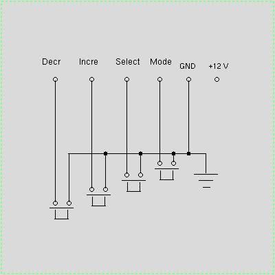
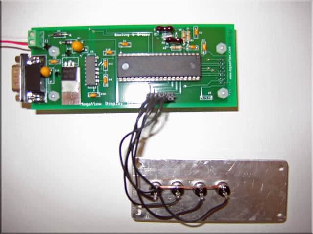
Install your buttons in the faceplate you’ve built– Line up the terminals on the back so that the two sets of terminals run parallel to each other. Use a bit of wire to connect one terminal from each of the buttons together and solder the connections. Then solder the wire from header pin 5 to this as a common ground for all buttons. (See pics below)
Wire the other buttons in any order you wish for them to be in– Pin 1 is the Decrement button, Pin 2 is the Increment Button, Pin 3 is the Select Button, and Pin 4 is the Mode button. Pin6 isn’t used, this is 12v+.
Here you can see my common ground I’ve run across all of the buttons and back to pin 5. Then the other terminals on the buttons go to each of pins 1-4.
Note— The MegaView works with all versions of the MegaSquirt ECU’s PCB: v1, v2.2, and v3.0. Though for v3.0 MegaSquirt ECU users you need to make sure your cable from the ECU doesn’t patch pin 9 through to the MegaView as this will cause a short. (Pin9 on the v3 is 5v, on the MegaView is ground.) The easiest solution is to use needlenose pliers and carefully remove pin9 from the DB9 connector on the MegaView. It will come out with just a bit of wiggling. That’s a simple, permanent solution. The pins are numbered if you look closely inside the connector.