If you haven’t already, please read the ‘disclaimer’ at the top of the parent page here.
Note – this adapter has been discontinued. This article is for legacy support.
What does this board do?
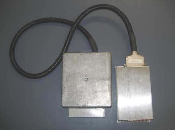
The EEC-IV adapter board kit allows you to install MegaSquirt into virtually any Ford vehicle that uses an EEC-IV computer, without cutting a single wire. Ford used the EEC-IV ECU from 1983 until 1995 in many of their US-market cars, including the 5.0 Mustang, Thunderbird Turbo Coupe, Merkur XR4Ti, pickup trucks, and countless Escorts, Tauruses, and many others. The EEC-IV adapter board bolts into an EEC-IV case in place of the original circuitry and connects to the MegaSquirt using a relay cable. You will just need to add a MAP sensor line to use Megasquirt’s MAP sensor.
The EEC-IV adapter board can work with most of the stock Ford hardware from this era. It can control the injectors, PWM fast idle valves, EDIS or TFI ignition, and drive relays and other circuitry as well. Since not all Fords use the exact same pinout, you can configure the adapter board using jumper cables to connect the injectors, oxygen sensor(s), relays, and the like. Several features, including the fast idle valve, ignition control, and temperature sensors, are the same on almost all EEC-IV units and do not require jumpers.
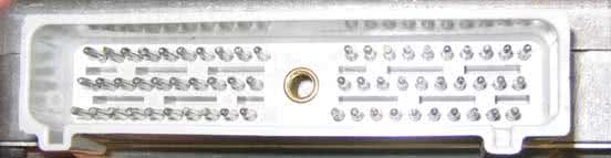
While the EEC-IV adapter board works with most injected Fords from this era, it does not work with all of them. A few early versions of the EEC-IV used a nonstandard connector. Some other Ford products used Mazda ECUs. Here is a close-up of the standard connector on the EEC-IV ECU.
Note, there are a few Fords from this era have some components that are a bit tricky. Some of the mid-’80s engines outfitted with CFI (central fuel injection) use a DC servo idle air control valve that does not work with Megasquirt. If you find one of these, you can simply adjust the idle speed screw to keep the car from stalling in cold weather and run without idle control. There are also a few distributorless ignitions that represented an intermediate step between TFI and EDIS. These use similar signals to the TFI system and might work with the TFI mods, but some specifics are not well documented or tested. This early DIS appeared on some versions of the Taurus SHO, Thunderbird Super Coupe, dual plug versions of the 2.3 inline four, and possibly a few other applications. A tip-off to the early DIS is that this early DIS did not use a 36-1 crank wheel trigger, while all EDIS systems have this trigger wheel. Also, some later Fords used computer controlled automatic transmissions. Right now, the code isn’t there to control these with the Megasquirt. The EEC-IV board has a second connector that you can use to make a pigtail harness that could let you hook up a stock EEC-IV ECU in parallel with the Megasquirt to control the transmission, although it may take a bit of experimentation to get this working right. You can also use a stand-alone transmission controller. Not all Ford automatics require electronic controls, however, or have the controls integrated into the EEC-IV ECU. ’93 and earlier 5.0 Mustangs, for example, do not use the ECU for automatic transmission control, and the EEC-IV adapter board in one of these cars does not present a problem.
The incompatible and/or challenging setups are few and far between, but worth a mention here. All standard TFI and EDIS Fords using an EEC-IV and a either manual transmission or an automatic with mechanical or standalone controls will work just fine… (86-93 5.0 Mustangs and various Escorts, Rangers, Tauruses, you name it…)
The EEC-IV has the PWM idle speed control driver already built in. You can simply use the standard fast idle control circuit on the MegaSquirt and set it up for PWM idle control in TunerStudio. It also simplifies the ignition input and output mods.
Complete schematics for EEC-IVadaptorV20sch
In this article, we will present a basic guide to how to set this board up for most common MegaSquirt versions. You will want to use a wiring diagram for your specific car to set up the jumpers.
Using the Megasquirt-I and EEC-IV Adapter Board with TFI
MegaSquirt-I PCBv2.2 Mods Required:
- Input mod: You install a 1k to 2k 1/4w resistor in place of D8
- Output mod: Run a jumper wire from the negative lead of LED 17 to pin 36 on the underside of the DB37 connector. On V2.2 boards, there is no hole on the board, so you must solder the jumper directly to the DB37 connector lead.
MegaSquirt-I PCBv3.0 Mods Required:
- Input mod: You install a 1k to 2k 1/4w resistor in place of D2. Jumper D1. Jumper TachSelect to OptoIn, XG1 to XG2, and TSEL to OptoOut.
- Output mod: Run a jumper wire from the top lead of D14 to the IGN jumper.
On the EEC-IV Adapter Board
- Use a 330 ohm resistor for R4, installed in the 12 volt position.
MSnS-E Ignition Configuration
- Configure TunerStudio for TFI Spark Output using LED17 (D14). Do not set any other spark outputs.
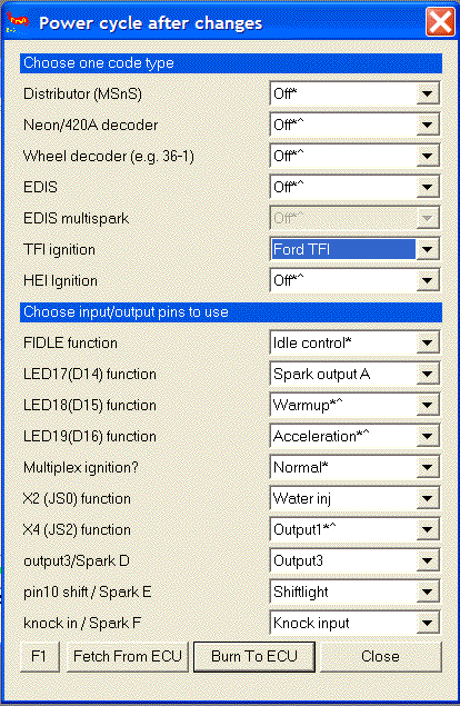
- Set Spark Output Inverted to Yes.
- Set Trigger Angle to 10 degrees.
- Set Dwell to Fixed Duty, and Spark Output Duty Cycle to 50% duty cycle.
- Note: This is for the “Push start” modules, without computer controlled dwell. The computer controlled dwell settings are not fully tested.
Using the Megasquirt-I and EEC-IV Adapter Board with EDIS
MegaSquirt-I PCBv2.2 Mods Required:
- Input mods:
- Remove the XG1 to XG2 jumper, D5, D8, and R10.
- Connect a jumper between XG1 and the right (non-banded) hole where D5 goes.
- Connect a jumper between the bottom hole in the R10 position and the right (banded) hole in the D9 position.
- Replace D8 with a 1.3k to 2k resistor.
- Output mod: Run a jumper wire from the negative lead of LED 17 to pin 36 on the underside of the DB37 connector. On V2.2 boards, there is no hole on the board, so you must solder the jumper directly to the DB37 connector lead.
MegaSquirt-I PCBv3.0 Mods Required:
- Input mods:
- Remove C30 and the XG1 to XG2 jumper if fitted, as well as any jumper running from TachSelect.
- Replace R12 with a 1.3k resistor. (Resistors from 1k to 10k should be OK).
- Run a jumper from S12C to the top hole in the C30 position.
- Jumper TachSelect to XG1.
- Jumper TSEL to OPTOOUT.
- Output mod: Run a jumper wire from the top lead of D14 to the IGN jumper.
On the EEC-IV Adapter Board
- Use a 2.2k ohm resistor for R4, installed in the 5 volt position.
MSnS-E Ignition Configuration
- Under Codebase and Output Functions, set EDIS mode using LED17 (D14) for spark output A. Do not set any other spark outputs.
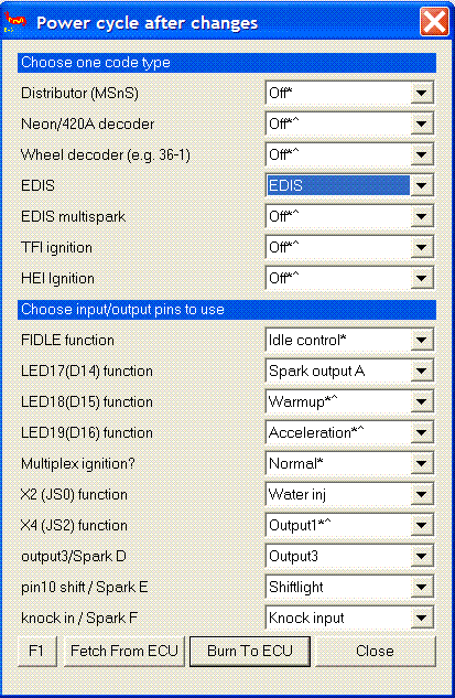
- Set trigger angle to 0 degrees.
- Set Spark Output Inverted to Yes.
- Set Dwell Control to Fixed Duty and 50% duty cycle.
Using the Megasquirt-II and EEC-IV Adapter Board with TFI
MegaSquirt-II PCBv3.0 Mods Required:
- Input mod: You install a 1k to 2k 1/4w resistor in place of D2. Jumper D1. Jumper TachSelect to OptoIn, XG1 to XG2, and TSEL to OptoOut.
- Output mod: Run a jumper wire from JS10 to IGBTIN and jumper IGBTOUT to IGN.
On the EEC-IV Adapter Board
- Use a 330 ohm resistor for R4, installed in the 12 volt position.
TunerStudio Ignition Configuration:
- Trigger offset = 10 (this will vary, depending on the distributor orientation, see below)
- Ignition Input Capture to ‘Falling Edge‘
- Cranking Trigger to ‘Trigger Rise‘
- Coil Charging Scheme to ‘Standard Coil Charging‘
- Spark Output to ‘Going High (Inverted)‘
Then set the dwell setting to 8.0 milliseconds with no battery voltage compensation. This will get the spark output to closely imitate the square wave signal that the EEC-IV computer sends out.
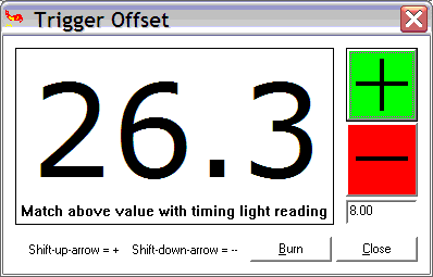
More information on setting Trigger Offset:
You must also set the initial position of the trigger (called the ‘trigger offset’), then check it using the Trigger Wizard in TunerStudio (Tools Menu). The trigger offset setting will vary according to your distributor position (where it is in rotation) but you’ll need to set it properly… Basically you use the Trigger Wizard and adjust the ‘trigger offset’ and/or twist your distributor until the advance number in the Trigger Wizard matches what you’re reading with your timing light. The +/- buttons on the trigger wizard will adjust your trigger offset. You’ll need to use these buttons and a timing light to make the number on your light, and the big number on the left in the Trigger Wizard, match up.
Here’s the information on this:
Before tuning your advance table, be sure to use a timing light to verify that your ‘trigger offset‘ is calibrated. Changing the Trigger Offset in TunerStudio will not change the displayed advance, instead, it changes the actual advance as seen with a timing light. Your goal is to make these two match.
To do this, get your engine warmed-up (otherwise the timing moves as the temperature increases) and idling, then use a timing light to verify to be certain your actual advance as shown by a timing light equals your the advance display on the advance gauge in TunerStudio. (8, in this case). (Note that positive numbers denote BTDC, and negative numbers denote after TDC.)
TunerStudio PWM IAC Configuration:
- First open the TunerStudio Configurator, and open CAR1>SETTINGS.INI>SETTINGS>IDLE_CONTROLLER and select PWM_GAUGE from the dropdown box at the top right.
- Save and exit the Configurator.
- Open TunerStudio and connect to the ECU, and from the SETTINGS menu choose IDLE CONTROL.
- Select the PWM Warmup Algorithm’ and then you can configure the values for your vehicle and click Burn to ECU’.
We do not have specific settings for all the Ford vehicles that you may be using this on.
Coolant (CLT) / Intake (IAT/MAT) Temperature Sensor Calibration
You can use your stock IAT and CLT sensors, and with the MegaSquirt-II you can calibrate these sensors through TunerStudio. It’s best to leave the standard R4 and R7 ‘Bias Resistors’ in place in the MegaSquirt and just configure this in the software. You get better accuracy this way.
- Open TunerStudio>Tools>Calibrate Thermistor Tables
- Select ‘Coolant Temp Sensor’, Select ‘Fahrenheit’, and enter these values:
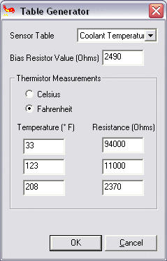
- Click OK and the Coolant sensor will be calibrated.
- You’re not quite finished yet though— You need to repeat these steps, but choose ‘Air Temperature’ as the sensor table and use the same temp and resistance values from above as the sensors use the same curve. This will calibrate the IAT as well.
NOTE– Make sure you chose Fahrenheit or your readings will be WAY off with the above values….
More Information
- Everyone should thoroughly read the MSExtra.com. www.msextra.com
- Read both the MS1 and MS2 sections, not all of the MS1 section will apply to you, but MUCH of it will, and the MS2 section isn’t really complete without this information.
You shouldn’t really ‘need’ this information, but it’s linked here for further reading if you’re interested.
Using the Megasquirt-II and EEC-IV Adapter Board with EDIS
MegaSquirt-II PCBv3.0 Mods Required:
- Input mod: Use the standard Hall/Optical input circuit. Jumper TachSelect to OPTOIN and TSEL to OPTOOUT.
- Output mod: Run a jumper wire from JS10 to IGBTIN and jumper IGBTOUT to IGN.
On the EEC-IV Adapter Board
- Use a 2.2k ohm resistor for R4, installed in the 5 volt position.
TunerStudio Ignition Configuration:
(from B&G’s EDIS Control page for the MS-II, modified for the different output circuit)
- Ignition Input Capture to ‘Falling Edge‘
- Cranking Trigger to ‘Calculated‘
- Coil Charging Scheme to ‘EDIS‘
- Spark Output to ‘Going Low (Normal)‘
TunerStudio PWM IAC Configuration:
- First open the TunerStudio Configurator, and open CAR1>SETTINGS.INI>SETTINGS>IDLE_CONTROLLER and select PWM_GAUGE from the dropdown box at the top right.
- Save and exit the Configurator.
- Open TunerStudio and connect to the ECU, and from the SETTINGS menu choose IDLE CONTROL.
- Select the PWM Warmup Algorithm’ and then you can configure the values for your vehicle and click Burn to ECU’.
We do not have specific settings for all the Ford vehicles that you may be using this on.
Coolant (CLT) / Intake (IAT/MAT) Temperature Sensor Calibration
You can use your stock IAT and CLT sensors, and with the MegaSquirt-II you can calibrate these sensors through TunerStudio. It’s best to leave the standard R4 and R7 ‘Bias Resistors’ in place in the MegaSquirt and just configure this in the software. You get better accuracy this way.
- Open TunerStudio>Tools>Calibrate Thermistor Tables
- Select ‘Coolant Temp Sensor’, Select ‘Fahrenheit’, and enter these values:
- Click OK and the Coolant sensor will be calibrated.
- You’re not quite finished yet though— You need to repeat these steps, but choose ‘Air Temperature’ as the sensor table and use the same temp and resistance values from above as the sensors use the same curve. This will calibrate the IAT as well.
NOTE– Make sure you chose Fahrenheit or your readings will be WAY off with the above values….
More Information
- Everyone should thoroughly read the MS2 Manual at MSExtra.com. This is your pride and joy… read the manual and the FAQ!!!
- Read both the MS1 and MS2 sections, not all of the MS1 section will apply to you, but MUCH of it will, and the MS2 section isn’t really complete without this information.
- Another great resource I refer to often is https://www.tunerstudio.com/
Relay controls, knock sensing, and more
The EEC-IV adapter board has several controls for relays to drive fans and other output circuits. These closely resemble the MSnS-E relay driver circuits with the addition of a LED to let you know when the circuit is active. To use these drivers, run a jumper wire from the appropriate source on the Megasquirt board to one of the IAC outputs, and run a jumper wire from the appropriate pin on the EEC-IV adapter board to the AxIN hole in the relay output area. Then run a jumper from the AxOUT hole to the appropriate pin on the EEC-IV connector. These outputs can drive relays by providing a ground.
The MSExtra manual section on relay outputs explains which area on the Megasquirt mainboard corresponds to which output number in TunerStudio. With Megasquirt-II, you use its spare output port settings to operate the relay drivers. In either case, you will just need one length of jumper wire inside the Megasquirt itself; the EEC-IV adapter board has the rest of the circuit.
For example, if you have a fan control circuit on pin 52 of the EEC-IV connector, and want to drive it from the JS2 port (that’s Output 1 on MS1/Extra, or a stepper IAC output on MS2) on the MegaSquirt, and use the A1 output on the EEC-IV board, you would wire JS2 to the IAC1A jumper on the MS, the IAC1A jumper on the adapter board to A1IN, and A1OUT to the pin 52 jumper.
The switch circuits work in a similar fashion. They’re designed to take a voltage input and send it to Megasquirt for table switching or nitrous control. In this case, the “In” side will go to the EEC-IV connector, and the “out” side to Megasquirt.
The EEC-IV adapter board also incorporates the knock sensor circuit from the MSExtra manual. You can wire its input to an external knock sensor and send its output through the relay cable to the appropriate pin on the Megasquirt. With MSnS-E, you will use pin 5 on the JP1 header for a V2.2 board, or the JS10 jumper on a V3.0 board. With Megasquirt-II, you need to use pin X6 for a V2.2 board or JP4 on a V3.0 board.
You can also use any of the other MSnS-E circuits and send their output straight from the Megasquirt to the EEC-IV connector by running the appropriate jumper wires. Note that the standard relay cable has the IAC wires, but not the four SPR wires.
The EEC-IV adapter board has a PWM IAC driver circuit. You can also have a PWM output circuit in the Megasquirt; in that case, leave out the PWM driver components and jumper PWM IN to PWM OUT.
V2.0 boards need you to run the thin jumper wire (included with the board) from the spot where R25 and R26 connect to a 12 volt hole in the proto area in order to make the PWM circuit functional. V2.1 boards do not need this jumper. To check if the board version you have needs this junper, measure the resistance from the connection between R25 and R26 to the 12 volt hole in the proto area. If it’s near zero, no jumper is needed.
Setting up the jumpers
To configure the jumpers, you will need a wiring diagram for the car you are installing your EEC-IV adapter onto. While the ignition, power, and temperature sensor lines are the same, you will want to check the pins for the injectors, oxygen sensor, and any relay outputs you may need to use.
Here are the jumper settings for one of the most popular EEC-IV cars ever, the ’86-’93 Mustang with the 5.0. This setup appears on the documentation; we have not tested it yet on an actual running 5.0 ourselves. This arrangement fires the #1, 6, 7, and 4 injectors on one bank, and the #2, 3, 5, and 8 on a separate bank. It only uses one oxygen sensor; you can add extra hardware to the Megasquirt for a second oxygen sensor output and change the injector connections to have each bank controlled separately, too.
| Connection | DB37 pin | EEC-IV connector pins |
| Injector bank 1 | INJ1 | 13, 15, 42, 58 |
| Injector bank 2 | INJ2 | 12, 14, 52, 59 |
| Oxygen sensor (right) | O2 | 29 |
We’ve also found that if you are preparing for a swap and want to check out your EEC-IV adapter board before you drop a 5.0 into a four banger car, you can make the 5.0 jumpers work on a ’88 2.3 Mustang (and quite probably other years) by disconnecting the EGR valve. As you may have guessed, we’re planning to put a 5.0 into our Mustang test car and test these settings out very soon – stay tuned!

The EEC-IV adapter board is also popular with the 2.3 Turbo crowd. On these cars, the ECU often controls the boost. Since there is no boost control provision in the EEC-IV adapter board, you’ll need to install our MK-Boost mod kit for boost control in the Megasquirt (see here for MS1/Extra & MS2/Extra) and bring its output to the IAC1A pin on a V3.0 / V3.57 board or X11 on a V2.2 (do not install the stepper IAC jumpers) if you want to retain this feature. Set up the board following the TFI directions above. Optionally, you may want to use the knock sensor input circuit on pin 31 (IAC2B or X14). The jumper setup below works for the following applications:
1983-1984 Ford Thunderbird Turbo Coupe and Mustang SVO
1989 Mercury Merkur XR4Ti
(no electronic boost control)
| Connection | DB37 pin | EEC-IV connector pins |
| Injector bank 1 | INJ1 | 58 |
| Injector bank 2 | INJ2 | 59 |
| Knock sensor (optional) | IAC2B | 23 (through knock sensor circuit) |
| Oxygen sensor | O2 | 29 |
1985-1986 Ford Thunderbird Turbo Coupe and Mustang SVO
1985-1988 Mercury Merkur XR4Ti
| Connection | DB37 pin | EEC-IV connector pins |
| Injector bank 1 | INJ1 | 58 |
| Injector bank 2 | INJ2 | 59 |
| Knock sensor (optional) | IAC2B | 23 (through knock sensor circuit) |
| Boost control | IAC1A | 32 |
| Oxygen sensor | O2 | 29 |
For the 1987 and later Turbo Coupe, the ECU controlled the fans. You’ll also need two generic relay control outputs on pins 27 (IAC1B or X12) and 29 (IAC2A or X13) for fan outputs on this model.
1987-1988 Ford Thunderbird Turbo Coupe
| Connection | DB37 pin | EEC-IV connector pins |
| Injector bank 1 | INJ1 | 58 |
| Injector bank 2 | INJ2 | 59 |
| Knock sensor (optional) | IAC2B | 23 (through knock sensor circuit) |
| High speed fan | IAC2A | 52 (through on/off output) |
| Low speed fan | IAC1B | 55 (through on/off output) |
| Boost control | IAC1A | 31 |
| Oxygen sensor | O2 | 29 |