Loading the Firmware onto your DIYPNP
This article will cover how to load firmware on your DIYPNP ECU, in a step-by-step manner.
Step 1 — Download the firmware
The first thing we’ll want to do is make sure we’ve downloaded the firmware version that we are planning to upload to the DIYPNP ECU. You can always find all of the MS2 Extra download files here:
http://www.msextra.com/doc/ms2extra/files/release/
The firmware versions are sorted on this page from oldest at top to newest at bottom. Generally speaking, you’ll want to choose the newest version of the firmware at the bottom. However, if you planning on using one of our start up maps for your application, you will need to make sure that you install into your DIYPNP the same firmware version that our start up map was built on in order for the base map to load in 100% clean with no errors. For example, if our start up map was built on 3.0.3H, and you wish to use our start up map, please load 3.0.3H into your ECU. Alternately you can choose a newer firmware version from the same series (maybe 3.0.3J for example, which would be a later release of the 3.03 firmware), and in many cases most all of the settings from our base map will load right in, though it may give you a couple warnings to review that often can be disregarded (though you should review them to verify).
If you are starting your own map from scratch, then choose the most recent release at the bottom. Download the firmware folder of your choice, make sure you unzip it, and move the folder to your C/Program Files/MegaSquirt directory for safekeeping and to make it easy to find later.
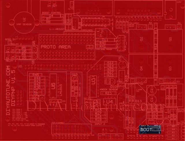
Step 2 — Installing the Boot Jumper
Next we will want to add the boot jumper to the ECU. The boot jumper is located near the bottom right corner of the main board. You should have soldered a 2-pin male header into the boot jump pins during assembly. What we’ll do here is add a cap/jumper on top of the standoff, which will short the two pins together and put the ECU into Boot Loader mode on the next power-up. If you did not install the header, you can use a small bit of wire or paperclip instead to jumper the two pins/holes together, just be careful not to short anything else.
Step 3 — Connecting to your DIYPNP ECU
Connect the DIYPNP to the serial port on your laptop. If your laptop does not have a serial port and you’re using a USB adapter, be sure that the adapter’s drivers have already been installed and is working properly before proceeding. Also make note of the COM Port that your USB Adapter installed to.
Now we’ll need to get 12 volts to your DIYPNP. The easiest and safest way to do this would be to use our power supply, which will plug into the ECU next to the DB15 jack. If you do not have a power supply and are using your car to power the ECU, be sure that power to your ignition coils are unplugged for the remainder of this procedure.
Close any open tuning software, as well as any other software which may want to use a com port. This can include PDA synch applications that may use a COM Port.
Step 4 — Flashing the DIYPNP Firmware
Open your C/Program Files/MegaSquirt directory and browse over to the firmware folder that you installed above. Open this folder, and then open the firmware loading program installed called “ms2loader_win32.exe” (for Windows – you’ll also find similarly named programs for Mac OS and Linux). If you are prompted by the ‘windows nanny’. Click Run.
This program will prompt you through the process. The program will first scan available COM ports. If it does not find one, you’ll need to open up your Windows Device Manager, and check under Ports (COM & LPT) the port assignment of your USB adapter. We recommend setting the USB adapter to COM4 or lower for best results. This can be done by right clicking on the USB adapter’s assignment, tabing over to Port Settings, Advanced, and then specifying a different, lower port number. You will have to click ok twice and close the dialog box.
It will ask you what device you are using. If it does not automatically detect this, select MicroSquirt Module. This is not the same as a cased MicroSquirt or an MSPNP – these have slightly different pin naming.
After the above prompt, the next prompt will ask about debug options. Press 1 for No debug.
The firmware installer at this point will begin loading the firmware into your DIYPNP. When finished, it will ask you to remove power from your ECU, remove the boot jumper, and supply power to the DIYPNP again.
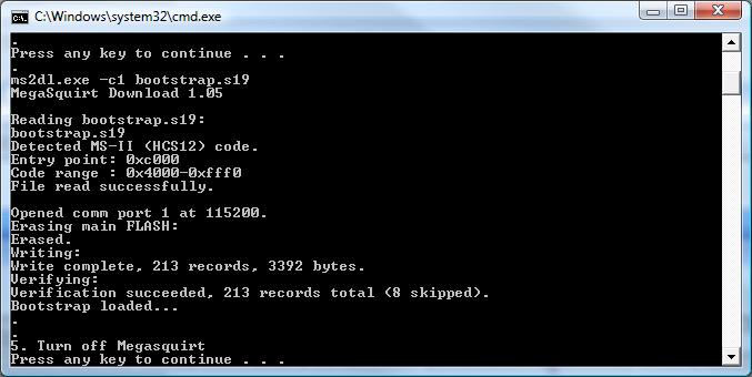
The firmware installer will then load firmware into your DIYPNP. This is what the screen will look like when finished.
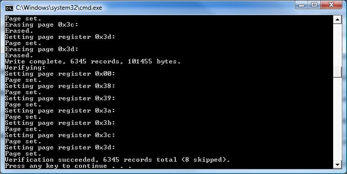
That’s it!! Your DIYPNP ECU is now loaded with firmware. You are now ready to begin configuring your basemap, or you can load one of our start up maps to help get you going in the right direction.