")


Description
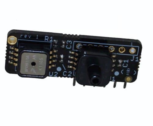
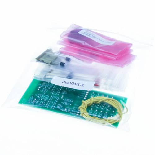
These are the parts needed for the ‘TIP120 PWM idle valve’ mod. If you are installing all optional components on the v3 heat sink (leaving no extra space for this transistor there) then you can drill a hole in your case and use it as your heat sink or add an additional heatsink on the bottom side of the PCB.
This kit will work with both the V2.2 and V3.0 PCBs. (Not needed on PCB 3.57 ECUs)
MS V3 Installation:
DO NOT install the small Q4 transistor that comes with the full ECU kit for use with PWM idle valves – it cannot handle the current directly for PWM idle valves. (‘On/Off’ type idle valves used with a relay are fine with the default Q4.)
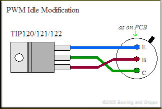
For a PWM idle valve use a TIP120/121/122 transistor (included in this kit) mounted on either the heat sink (if you have a spare spot) or the case. You should use a mica insulator with heat sink grease (both also included). Run wires to the Q4 location as shown below:
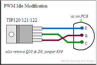
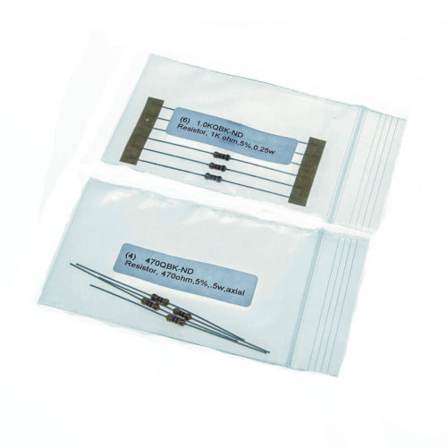
Do not install (leave unpopulated) Q20 or D8. Jumper across R39 as well. You will also have to put the 1N4001 diode (included) across the PWM Idle valve itself – the banded end goes to the 12 Volt supply, the non-banded end goes to the pulsed ground signal lead that goes to MegaSquirt. This diode is for voltage flyback purposes.
MS V2.2 Installation:
Replace transistor Q5 with the TIP120/121/122 transistor. You should mount the transistor to the case using the included mica insulator and heat sink grease. Wire it to the board as shown:
You do not need any further modifications to the board or external wiring when installing this with a V2.2 board.
Wiring and Configuration
To wire this up without the relay board (directly to the ECU), wire up the hot wire from the idle valve to switched 12v+, and wire the negative wire from the idle valve directly to pin 30 on the MegaSquirt DB37.
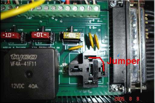
To wire this up with the relay board, you will need to jumper the FIDLE relay to take it out of the loop; below is a picture of how to do this. Then you will still wire up the hot wire from the idle valve to switched 12v+ (you could use the fuel pump power from the relay board), and wire the negative wire from the idle valve directly to the FIDLE terminal on the relay board. This will allow full control of your PWM idle valve.
Software settings for MS1
Information on tuning these settings can be found in the MS1 manual by clicking -here-.
Software settings for MS2
Information on tuning these settings can be found in the MS2 manual by clicking -here-.

Reviews
There are no reviews yet.